


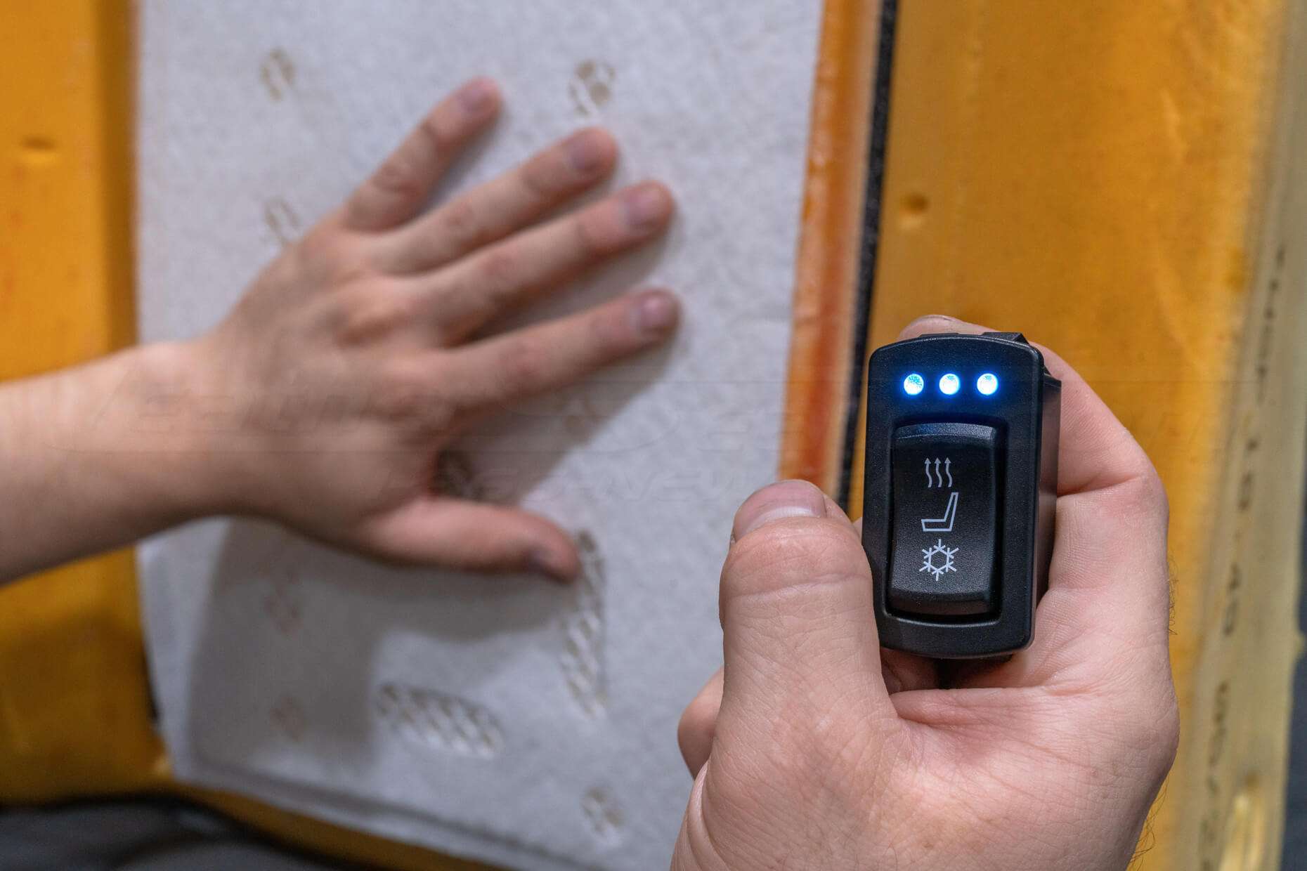
Our Sanctum Seat Ventilation System provides an integrated, adjustable climate control option for your seats. This system utilizes ThermoElectric Devices that can be installed in any vehicle with a 12-volt source and installs flush with the seat cushion underneath the upholstery. Each ventilation kit is designed for one seat so if you would like both of your front seats to have seat heaters, you will need to purchase two kits.
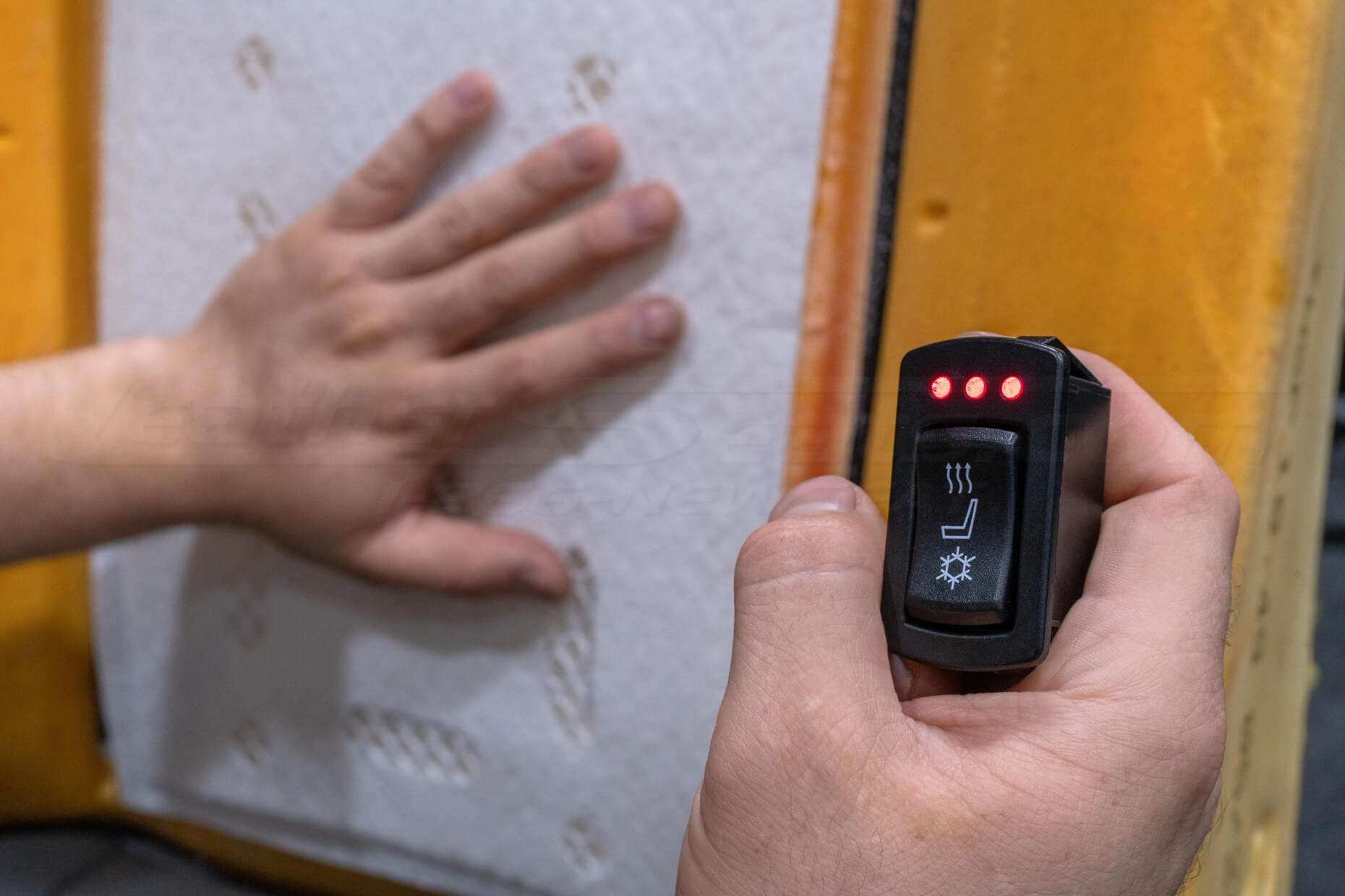
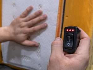
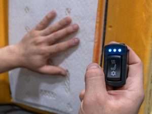
This system features 3 levels of seat heating and cooling in one single switch. This system will replace any factory seat comfort system and is compatible with our LeatherSeats.com upholstery kits with perforation and a high-flow reticulating backing foam.
A few notes about our system.
- Requires a 12v power source
- Requires room and accessibility to mount all components to the seat
- Requires upholstery that supports proper air-flow
- Replaces any existing seat heaters
- We suggest using a circuit with a minimum of 15 amps per unit
A few notes before you begin.
- Layout all of the components that you received to make sure that you have all of the parts and tools ready for installation.
- Do not install these units on top of surface-mounted occupancy detection sensors.
- Only install these units under upholstery that is in good condition with no rips/tears that would expose the distribution pads.
- Any time you disconnect the power to your seats or work with a vehicle’s electrical systems, always disconnect the main battery to avoid error codes, electrical shorts, and in extreme cases, cause the airbags to improperly deploy.
*This product requires advanced knowledge of automotive electrical systems and may require heavy modification or fabrication to the seat for proper installation. We do not include vehicle-specific wiring or installation instructions as every application will vary. If you are not capable of installing the product, professional installation is highly recommended.
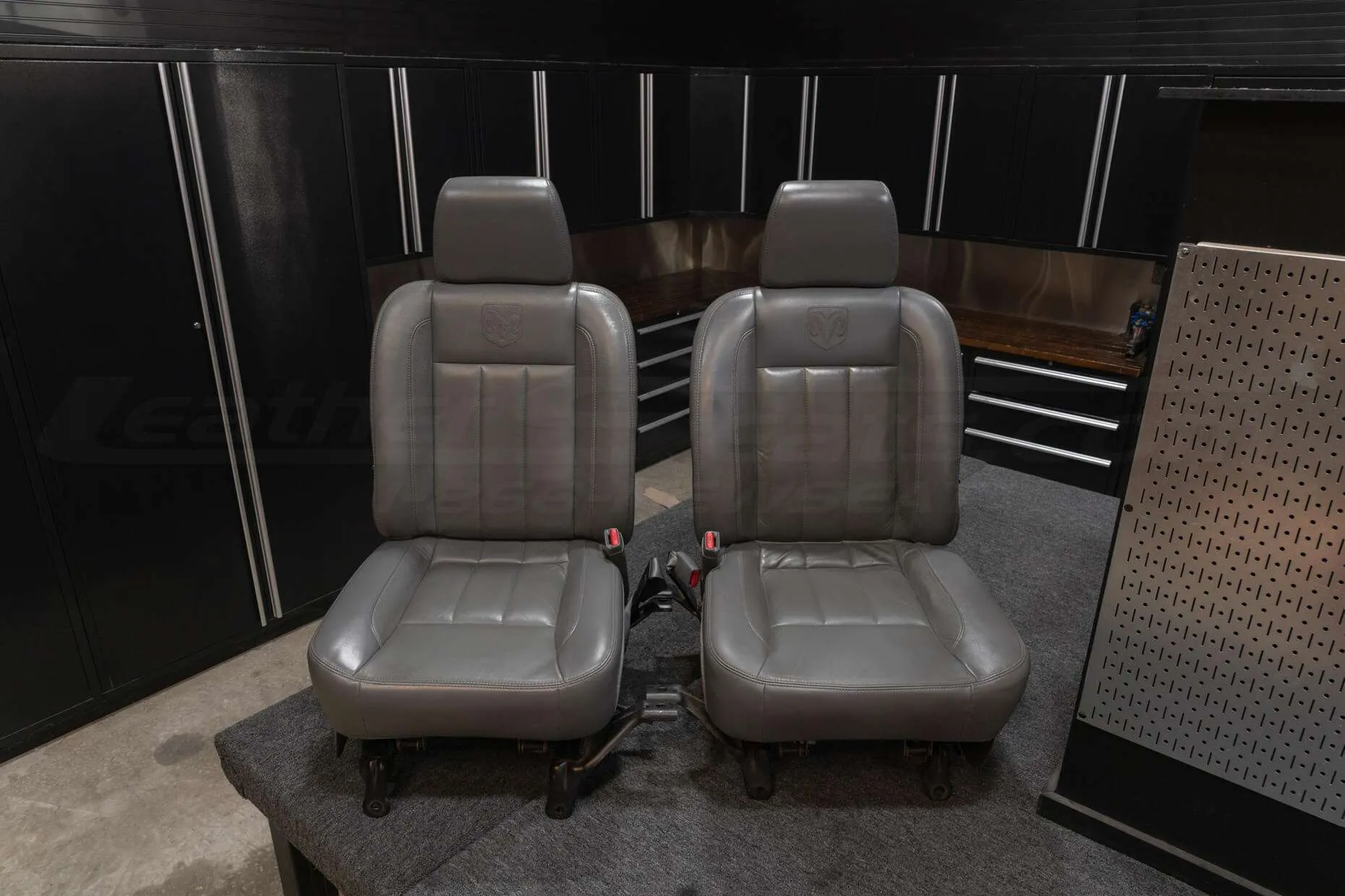
Remove Seats From Vehicle
Before removing the seats from your vehicle or servicing any electrical systems, disconnect the vehicle’s battery to ensure the working area is grounded. Unbolt the seats and unplug all power wires and connectors going into the seats. To help avoid scratching the interior plastics or door panels when removing the seats, we recommend covering the door and floorboard with blankets or towels.
Any time you disconnect the power to your seats or work with a vehicle’s electrical systems, always disconnect the main battery to avoid error codes, electrical shorts, and in extreme cases, cause the airbags to improperly deploy. Save any radio security codes before disconnecting the battery.
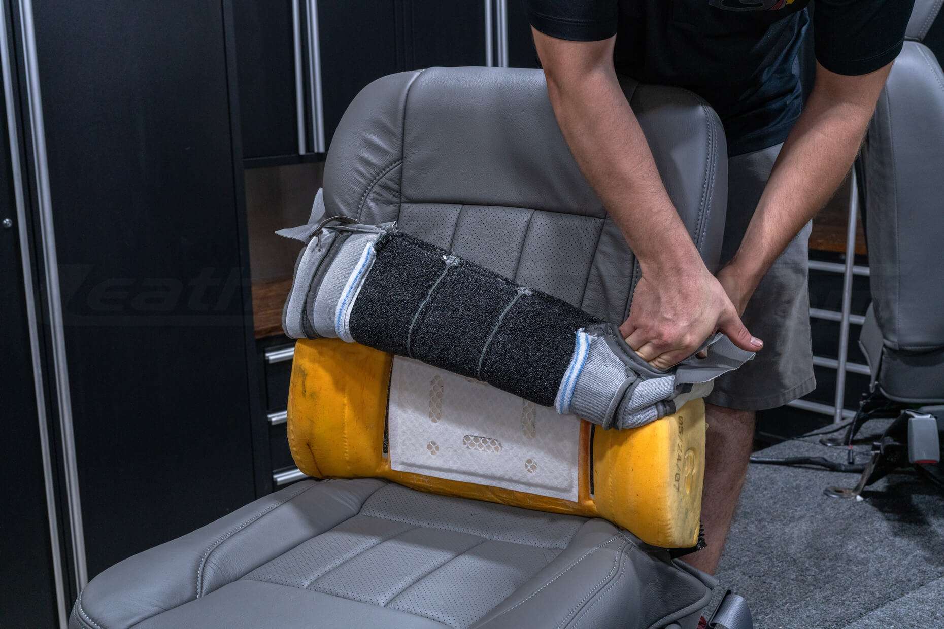
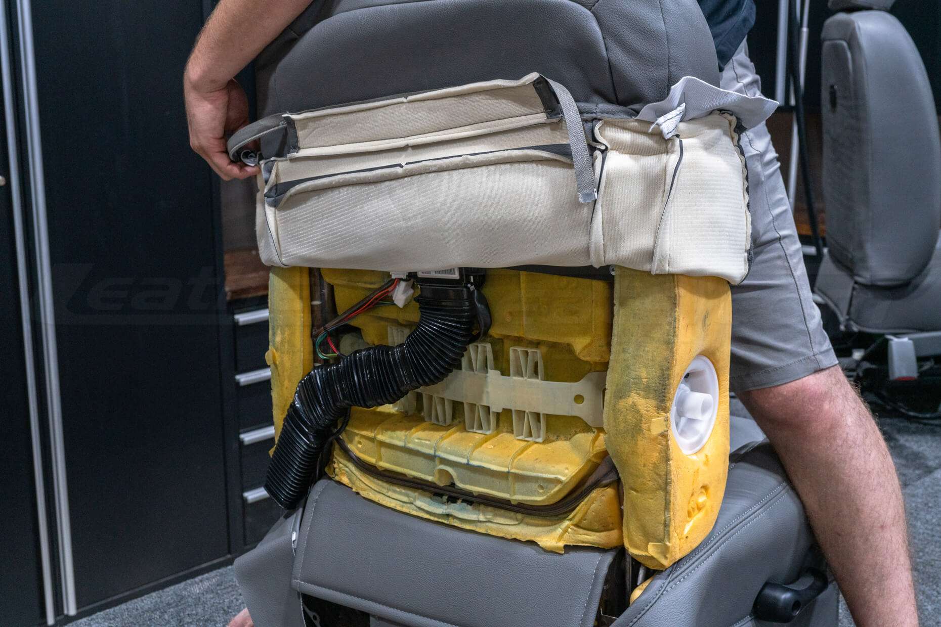
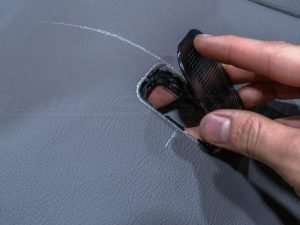
Remove Upholstery From Seats
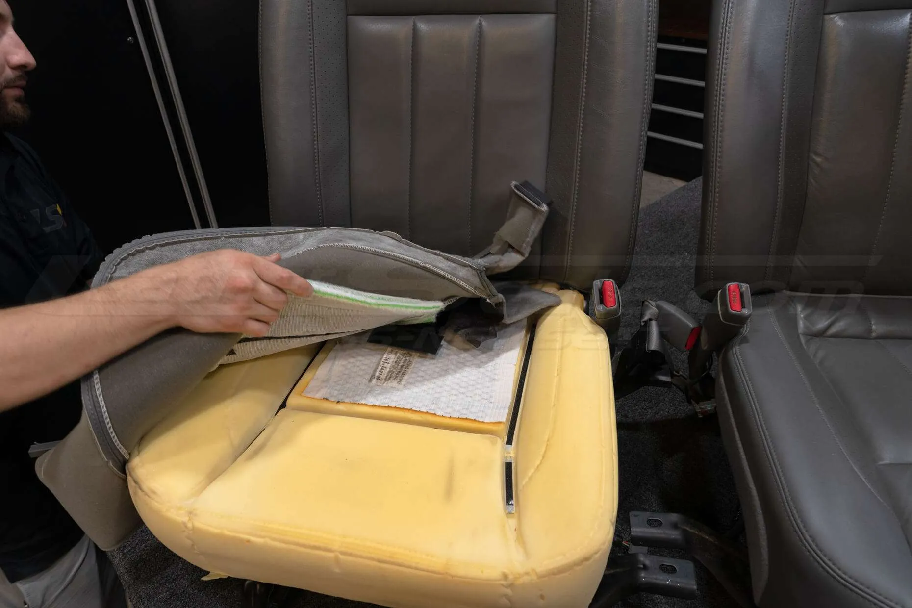
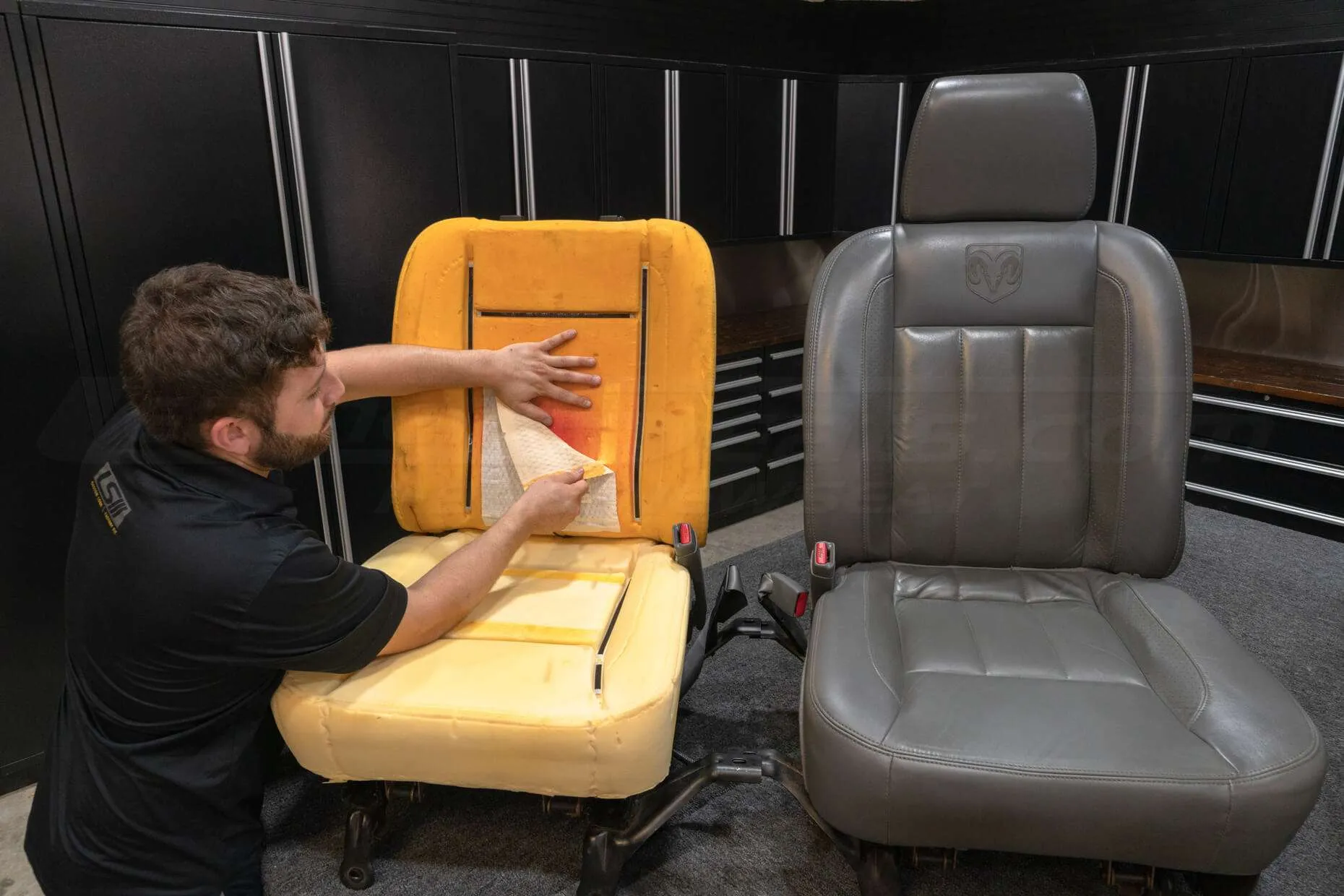
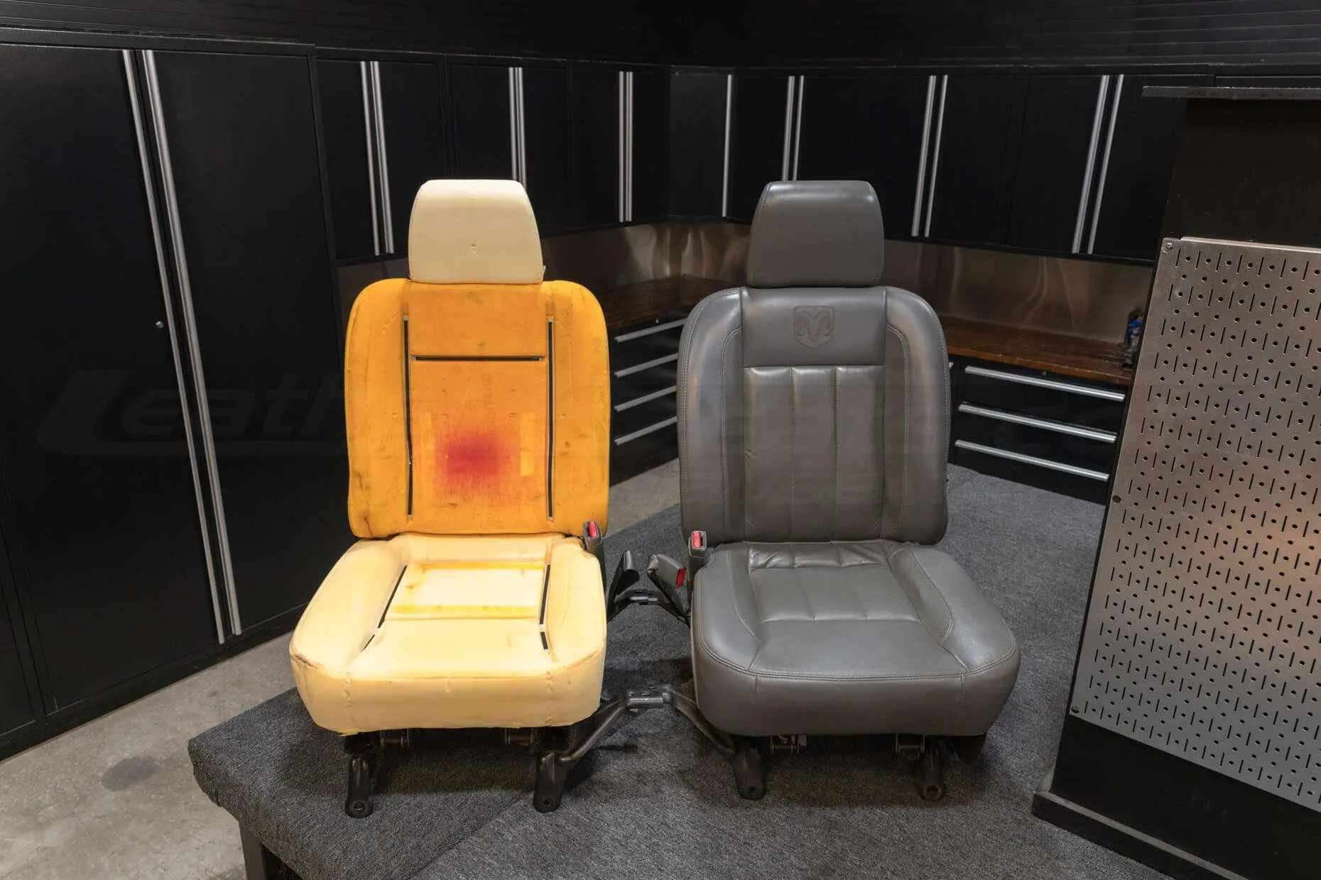
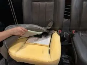
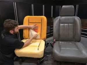
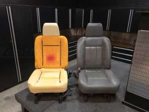
Removing the cloth or leather upholstery from the seats will vary with every vehicle and typically requires basic hand tools. You may also need to remove the side plastics to gain access to the upholstery attachment points. A good practice is to take notes and/or pictures of the seats throughout this process so that you know how everything goes back together when you go to reinstall the upholstery.
If your vehicle is equipped with seat heaters, they will also need to be carefully removed before installation.
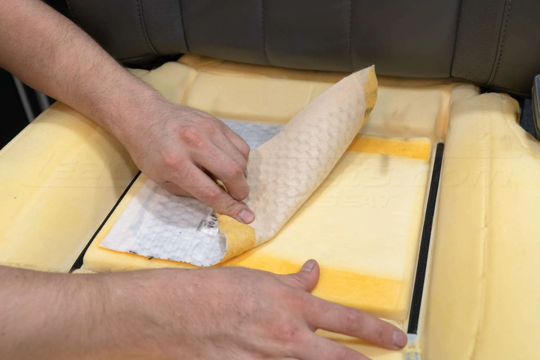
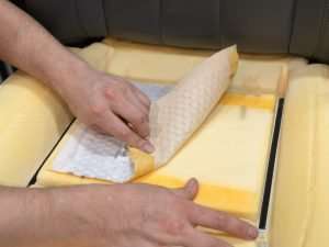
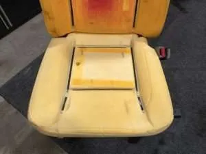
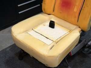
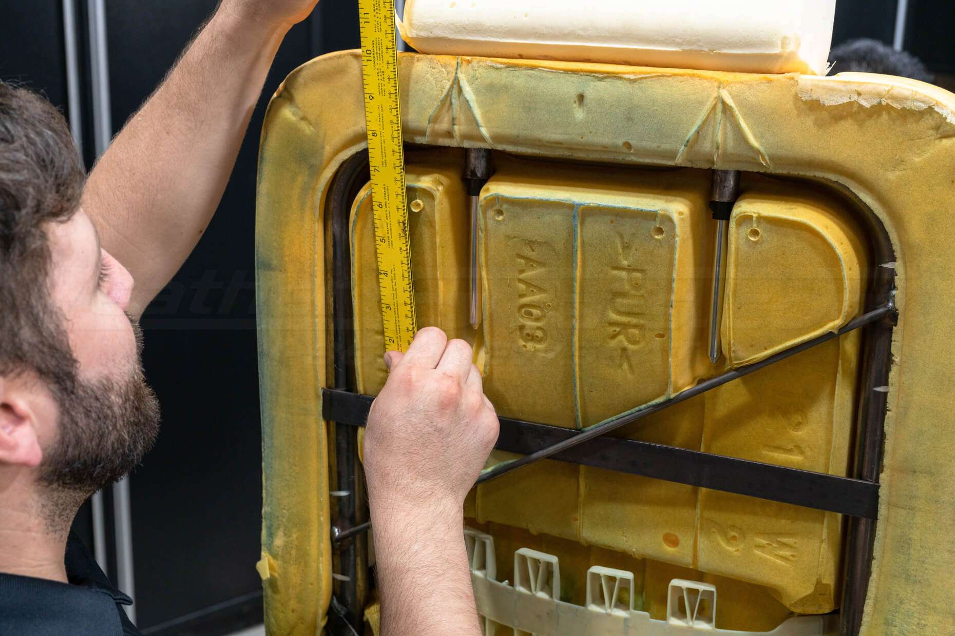
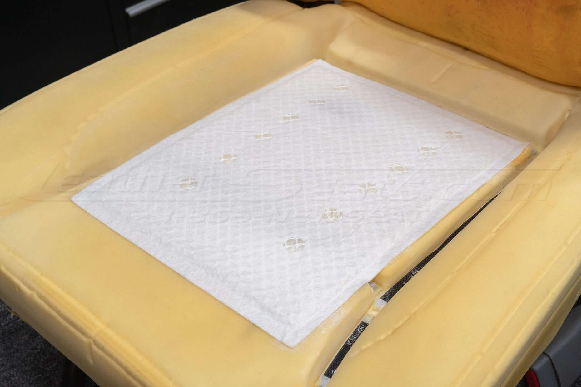
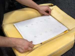
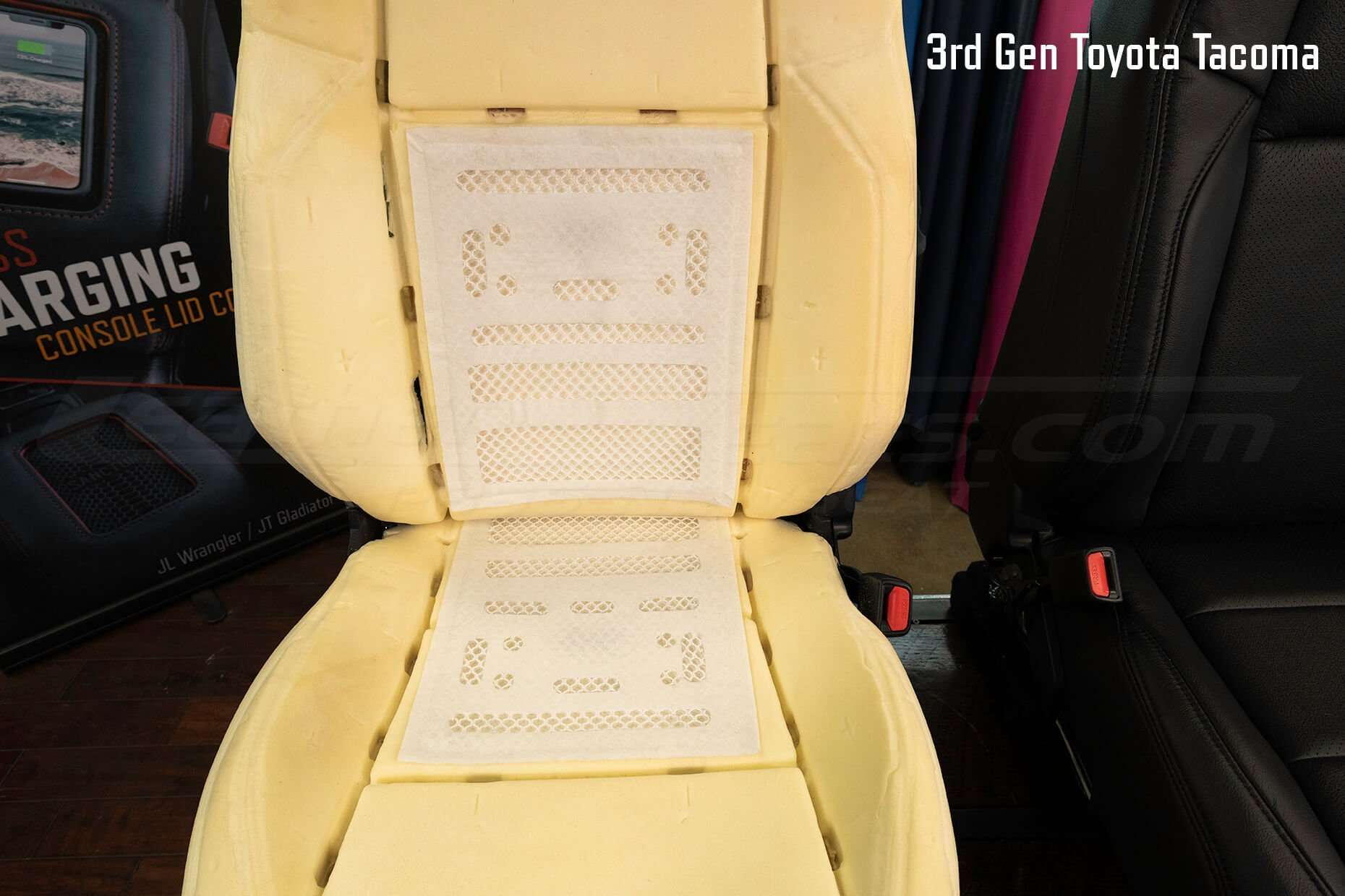
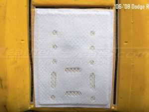
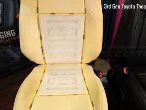
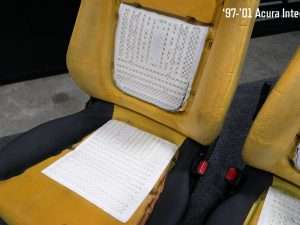
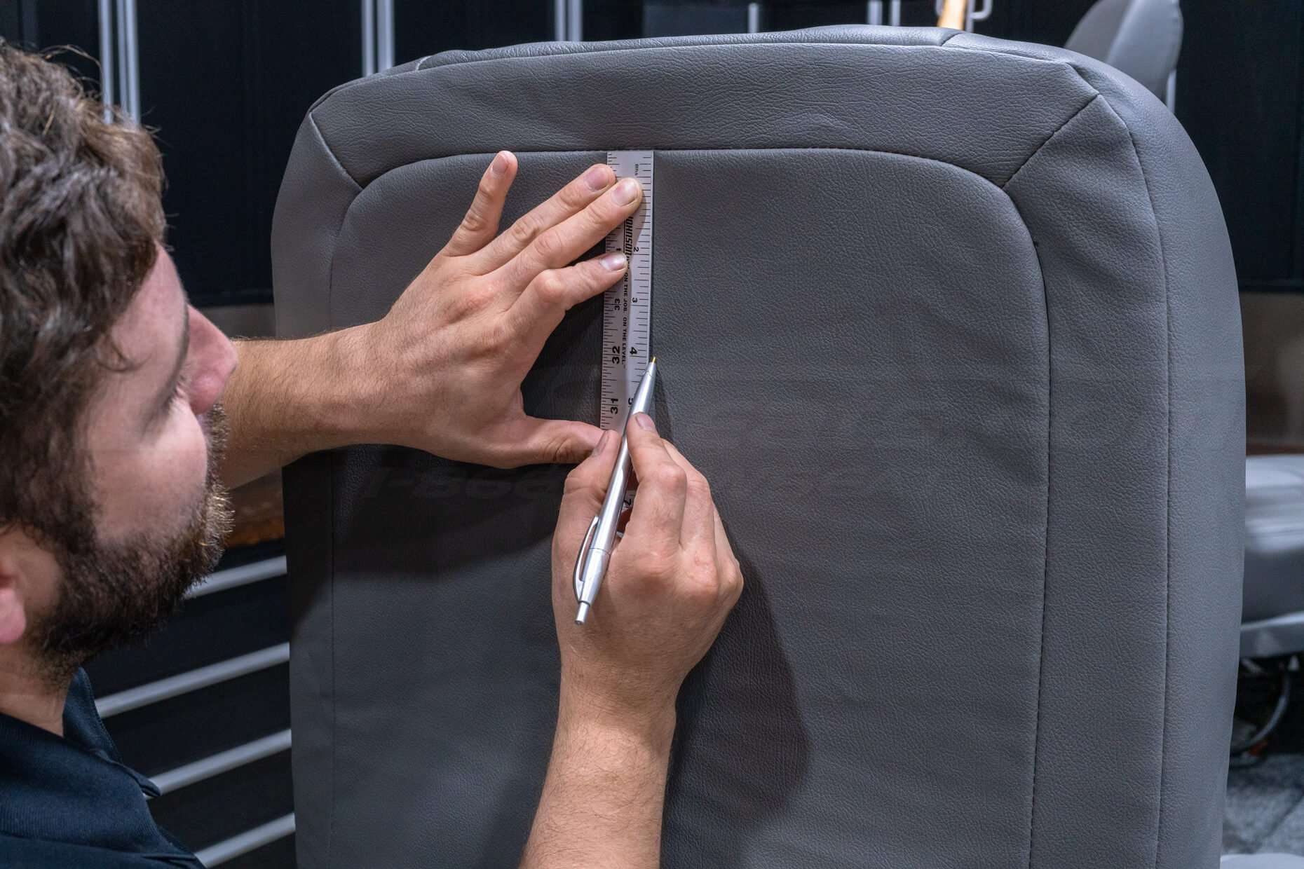
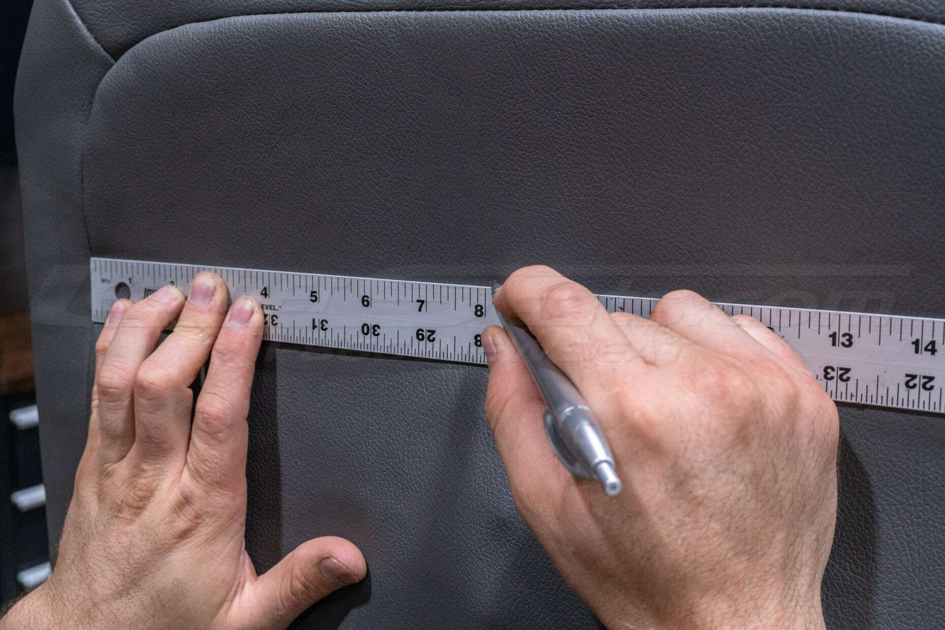
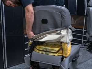
Determine Pad Placement/Modify Size
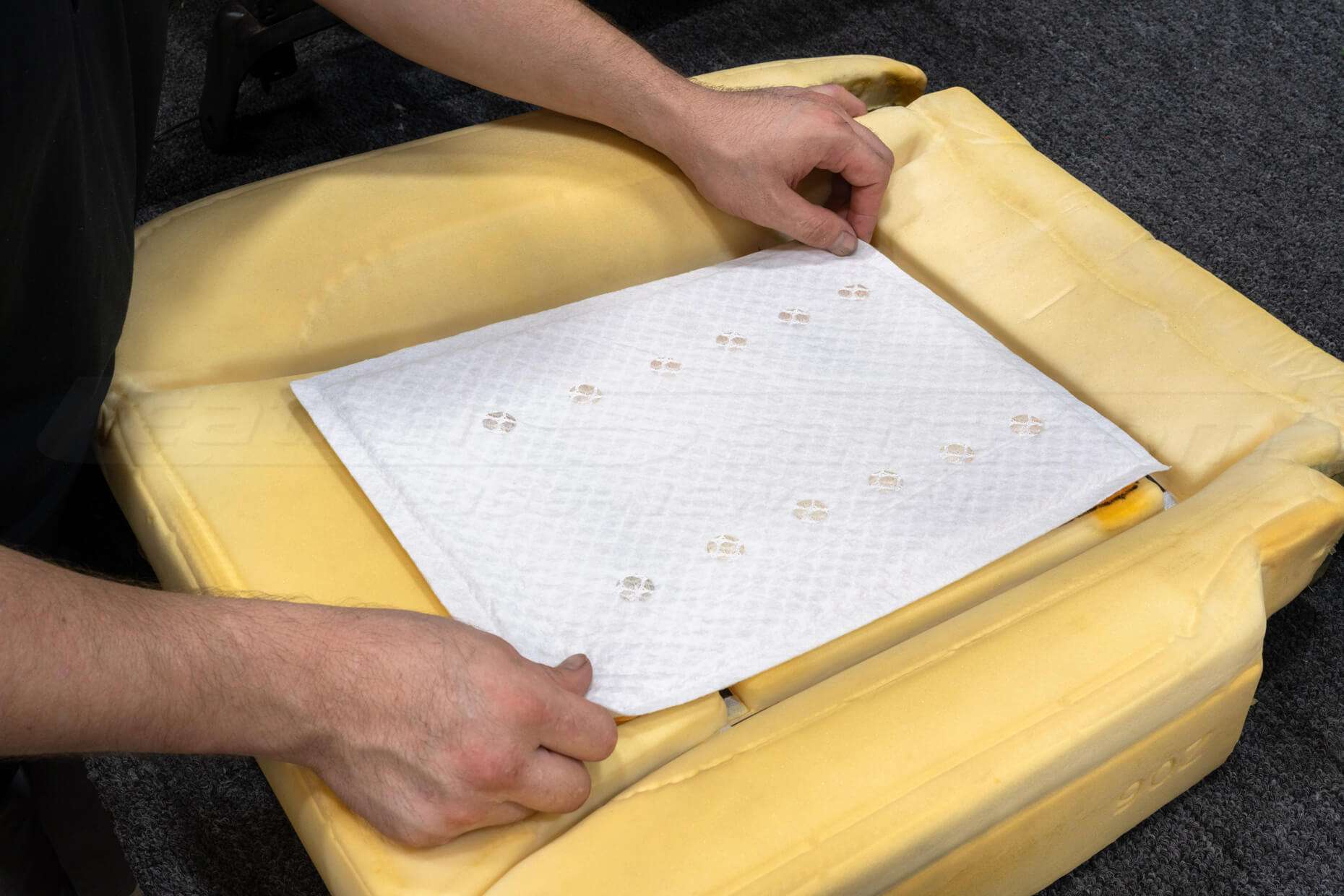
You will need to decide where on the seats the air distribution pad will be installed. Depending on the seat pattern, there may be some upholstery listing attachments that are covered. In some cases, it may be necessary to “float’ a listing attachment and only use one of the attachment points.
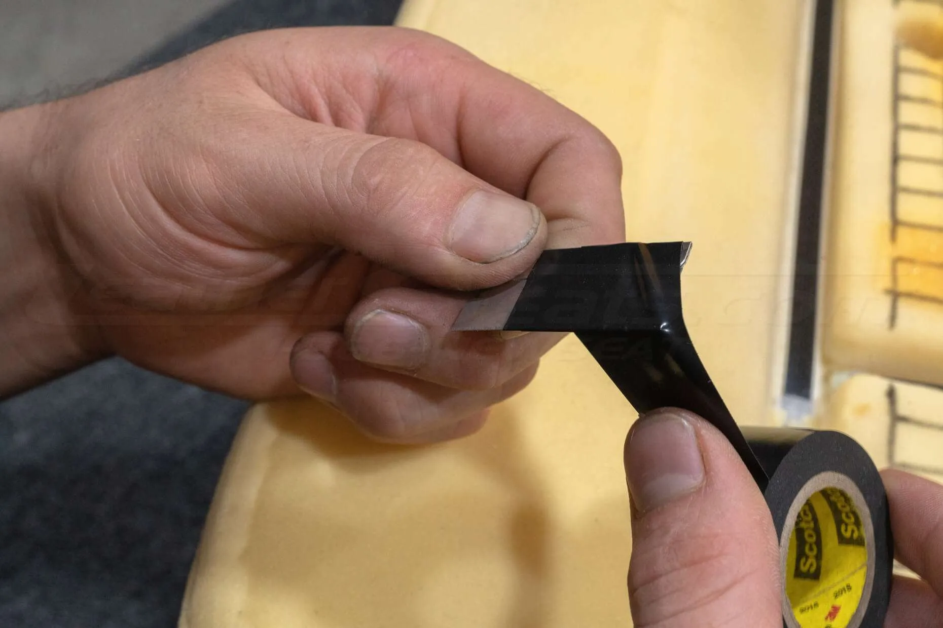
The air distribution pad can be cut down and modified in size. Once cut, the sides of the pad will need to be resealed.
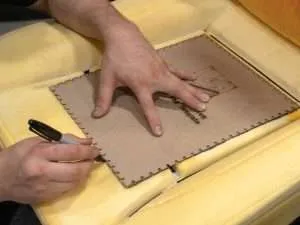
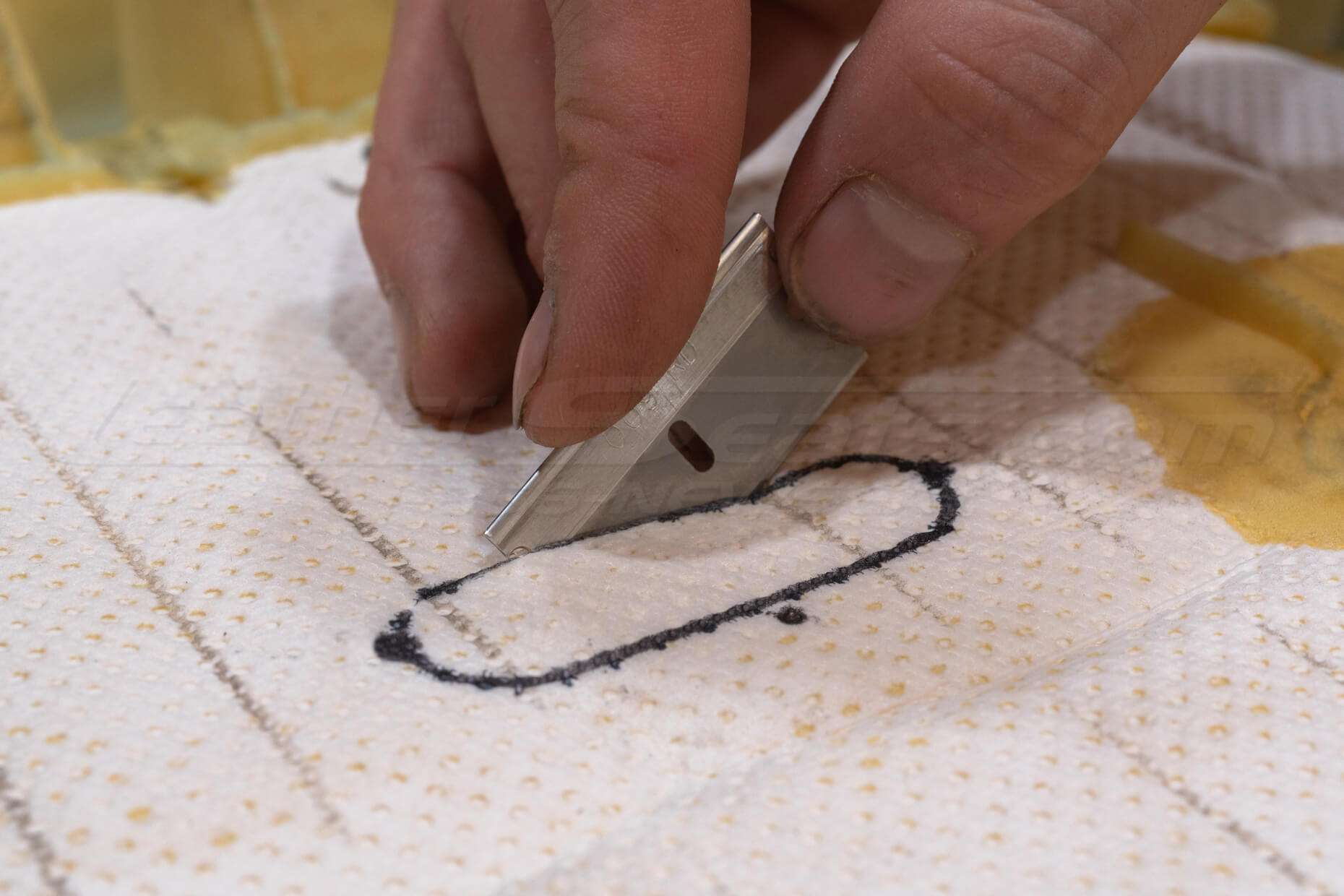
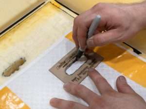
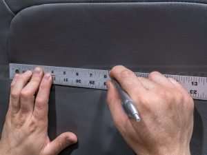
Once the placement of the air distribution pad is determined, trace where the pad will lie on the seat foam using our template or the pad as a guide.


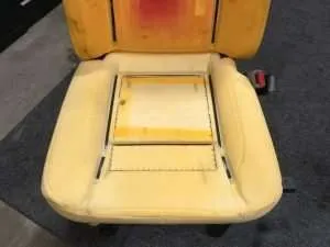
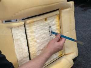
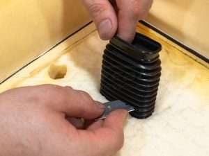
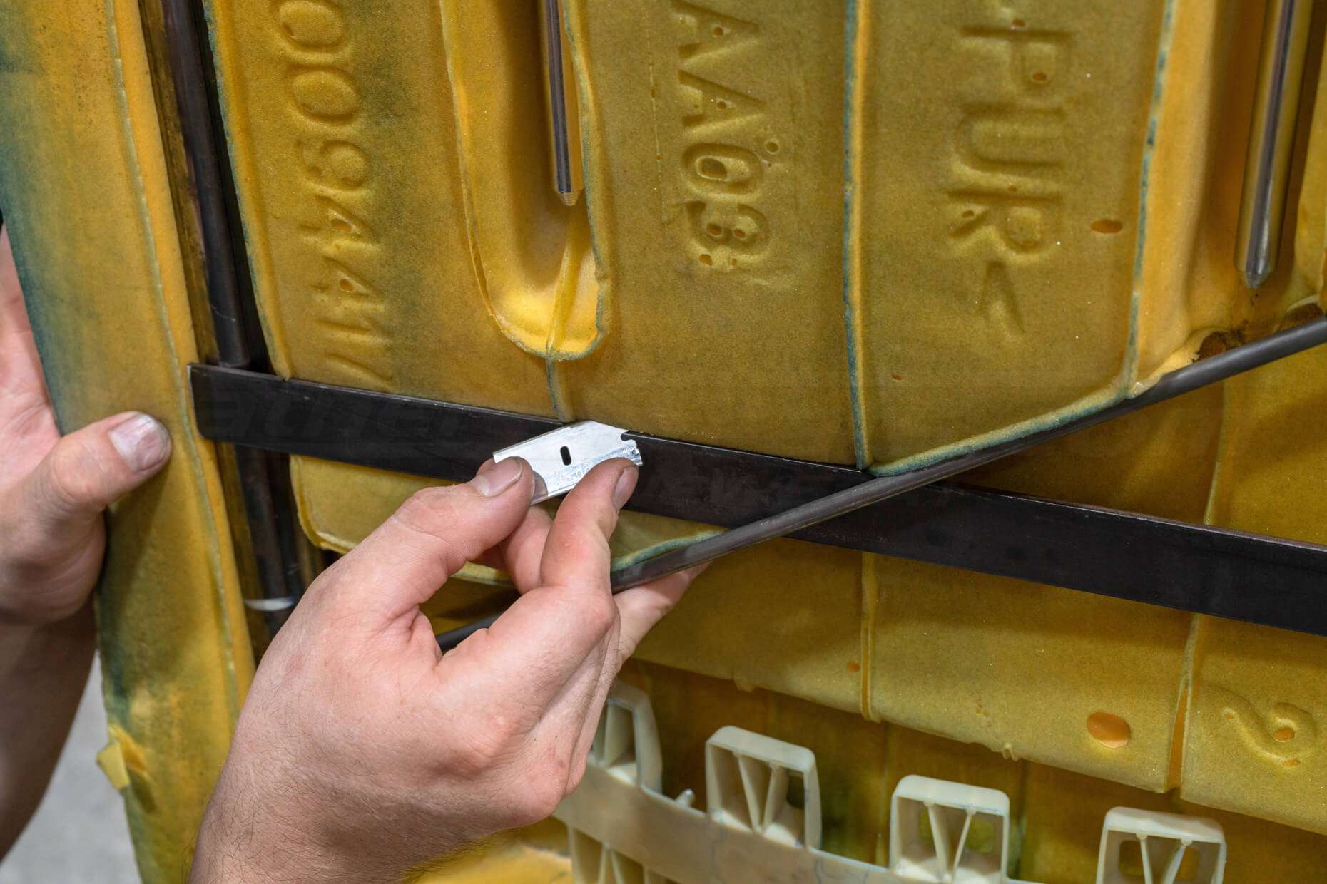
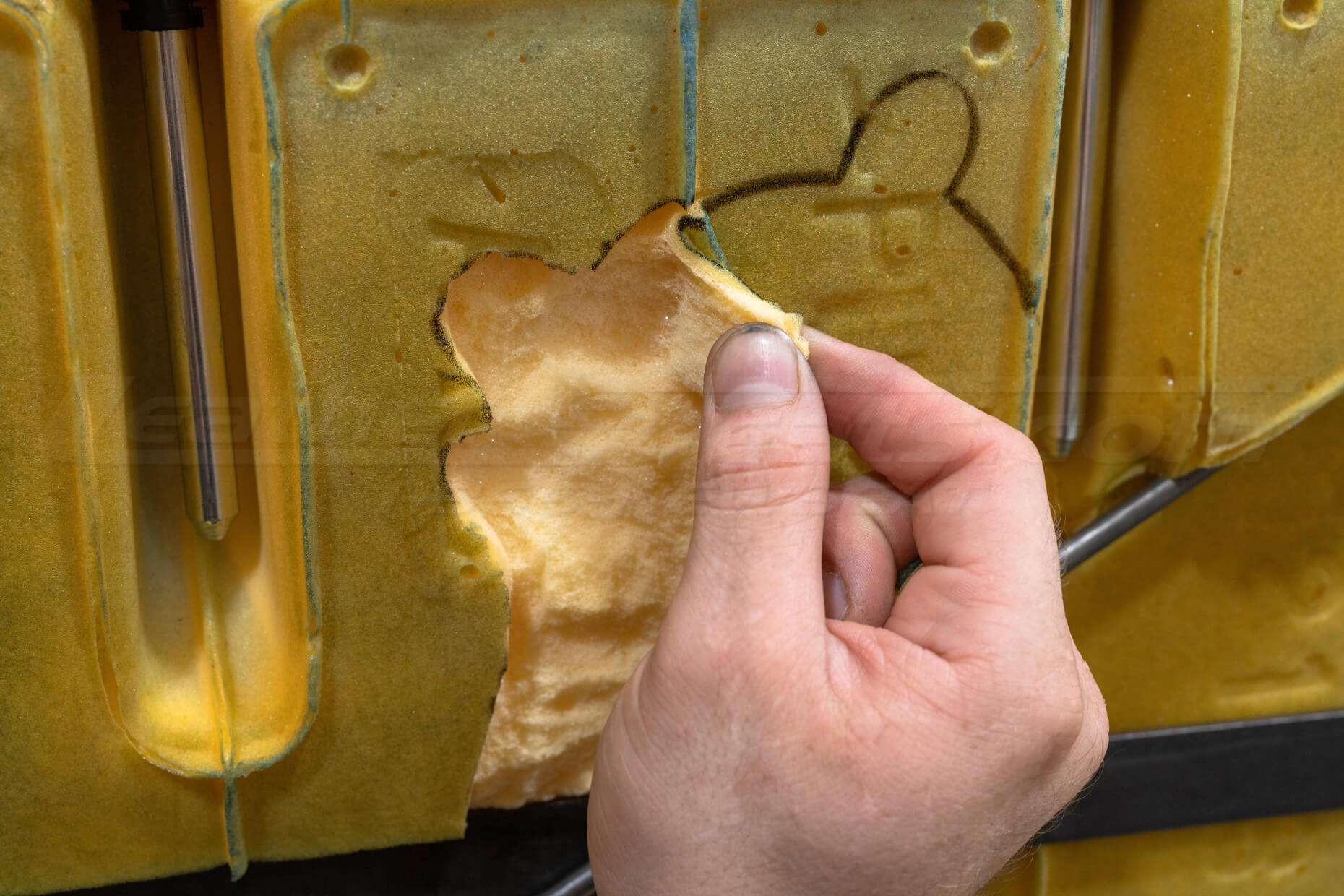
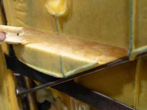
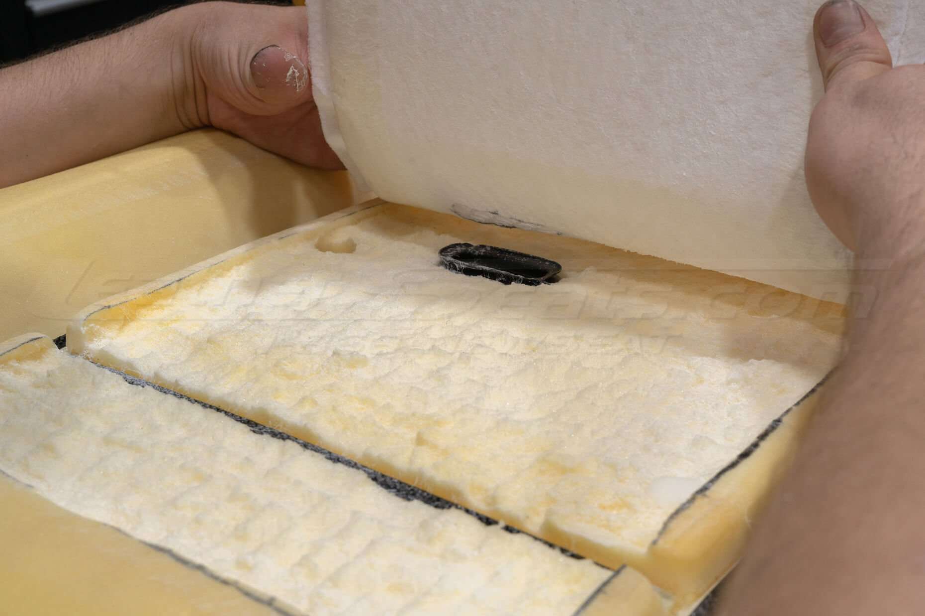
Trench Seat Foam For Pad


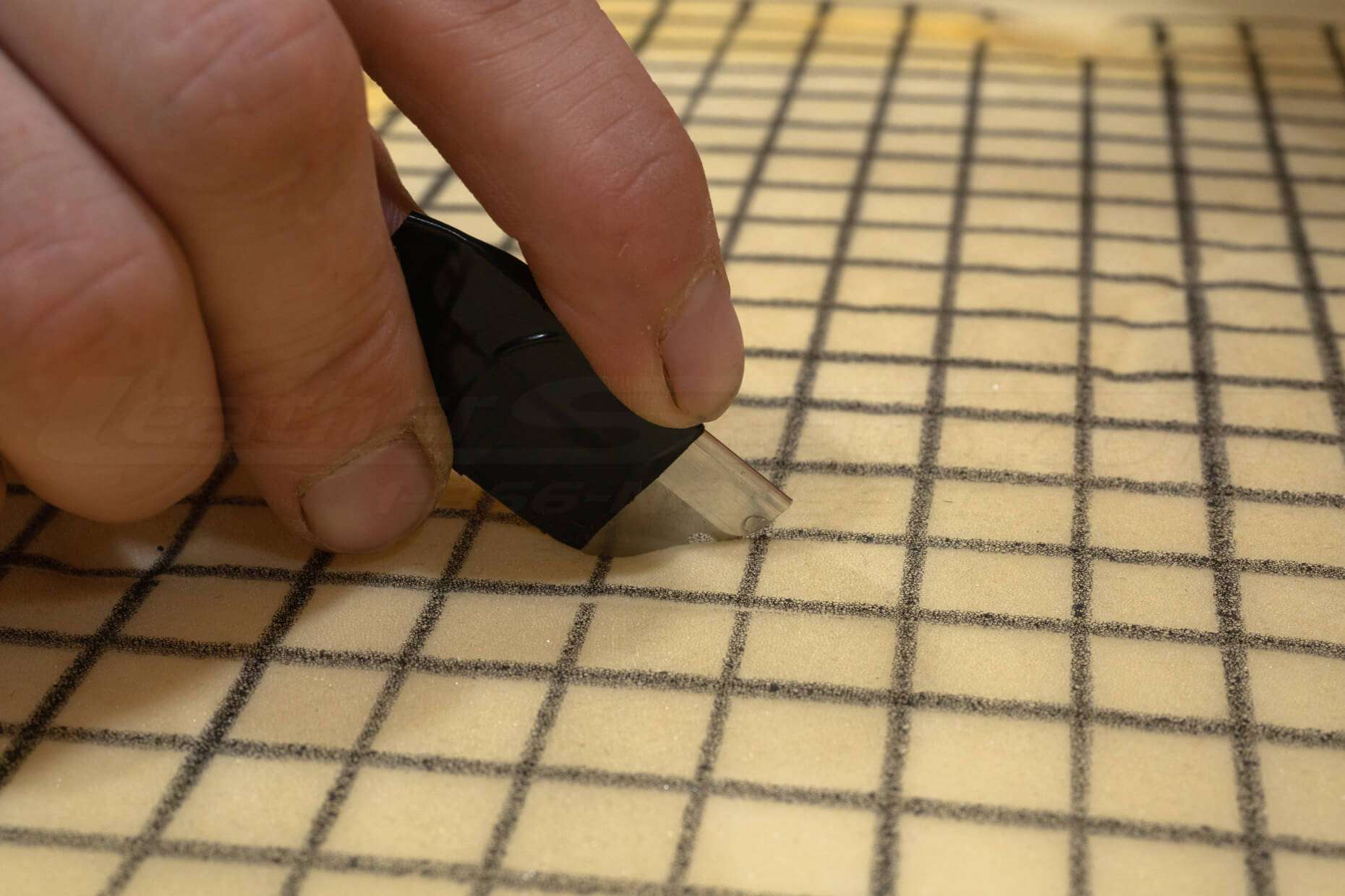
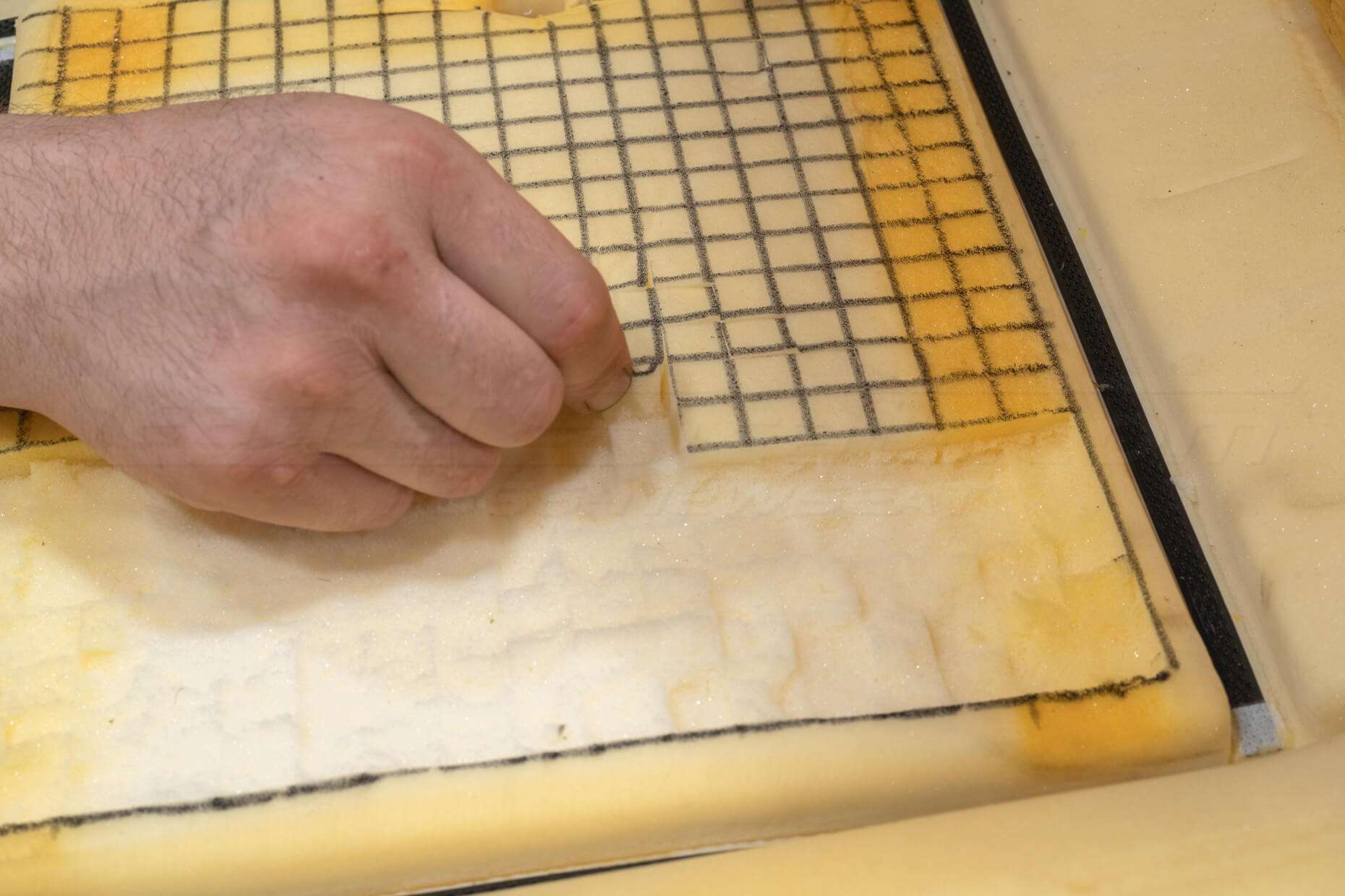
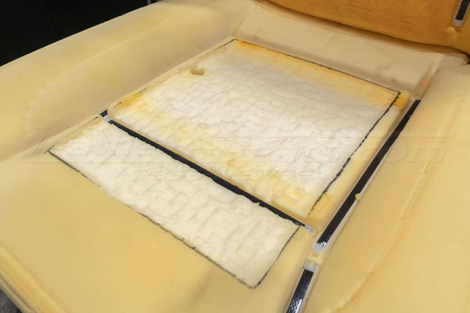
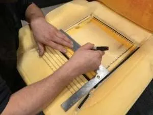
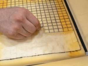
Use a router or razor blade to trench out the seat foam ⅜” to allow the distribution pad to lay flush with the seat foam.
(Optional) Use an angle grinder or sandpaper to smooth out the seat foam.
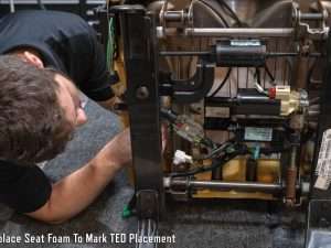
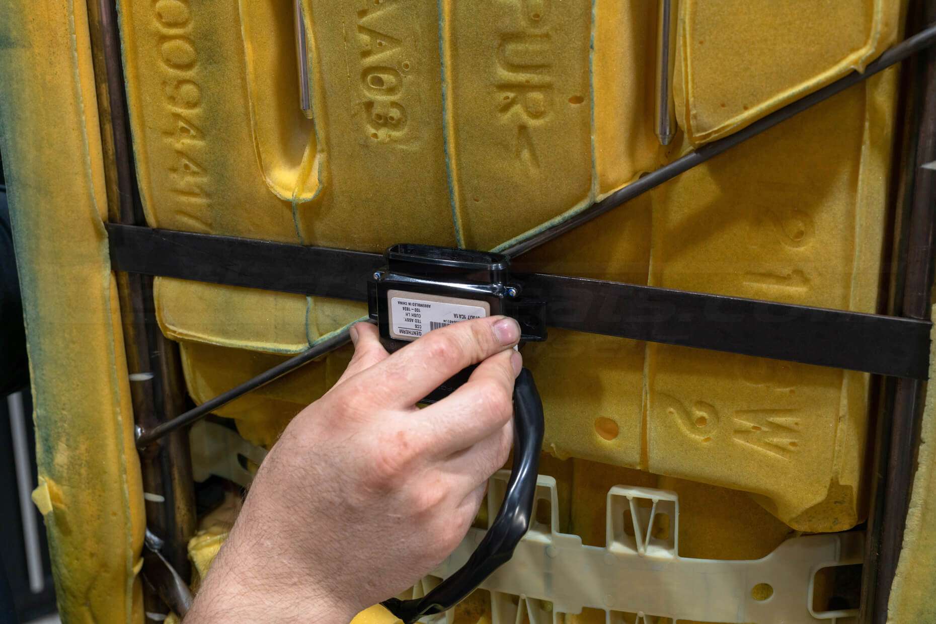
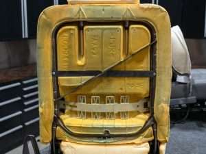
Determine TED/Blower Placement
Ideally, the TED unit should be as close to the center of the distribution pad as possible. If the center is not directly accessible on the other side of the seat foam, mount the TED unit as close to the center as you can.
Some seat components may need to be modified in order to mount the TED and Blower. Every seat is different and you may need to get creative on how the units are mounted.
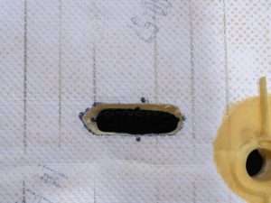
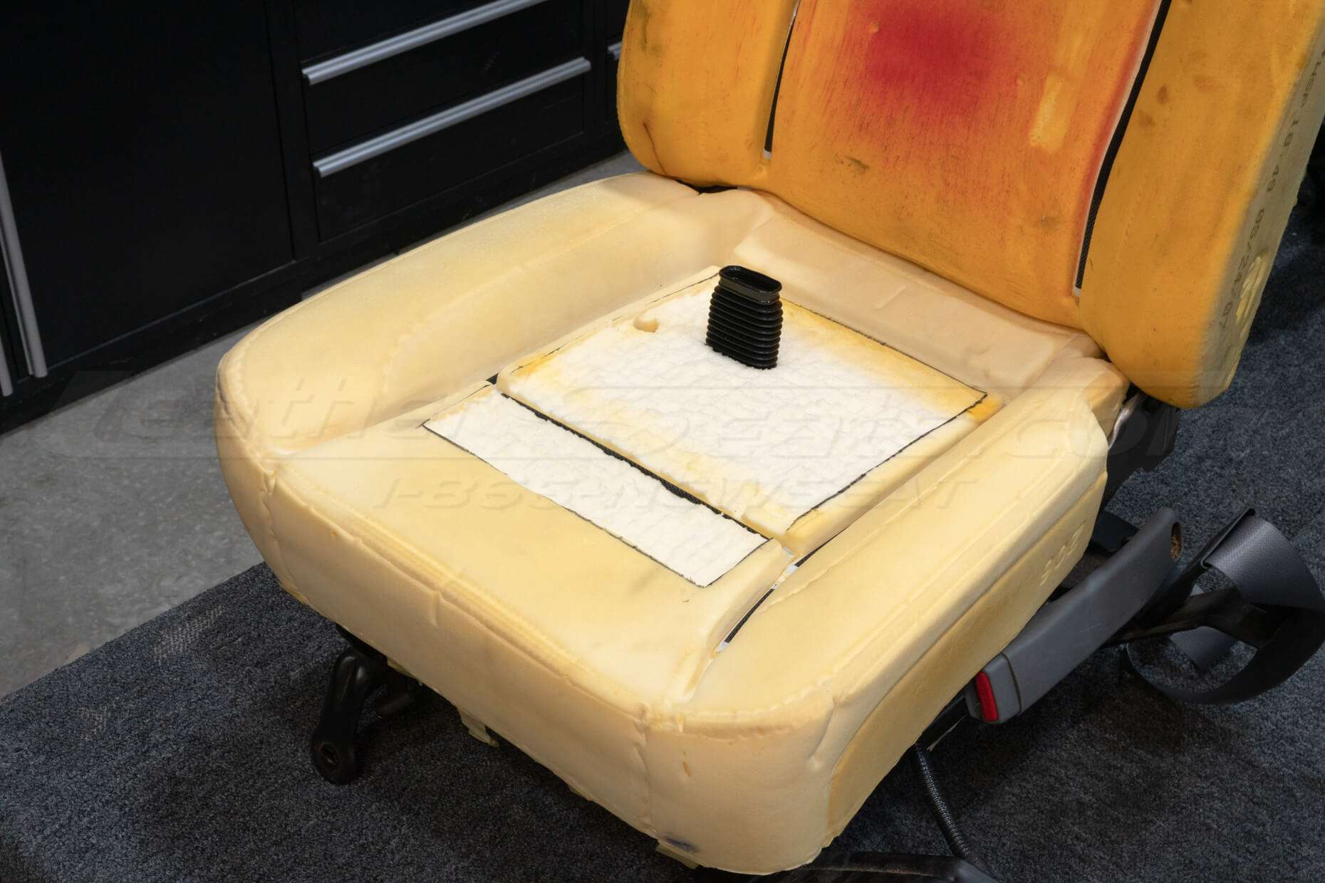
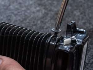
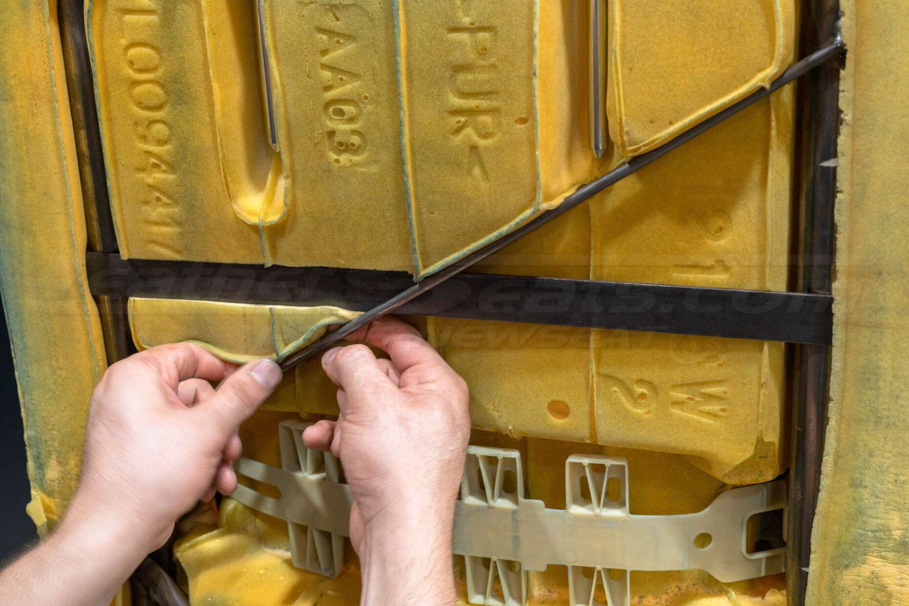
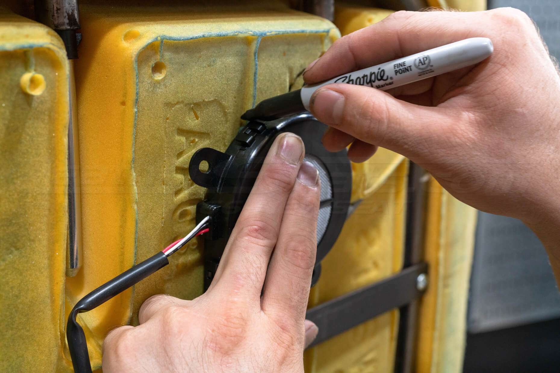
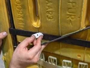
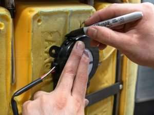
Trace Hole For TED
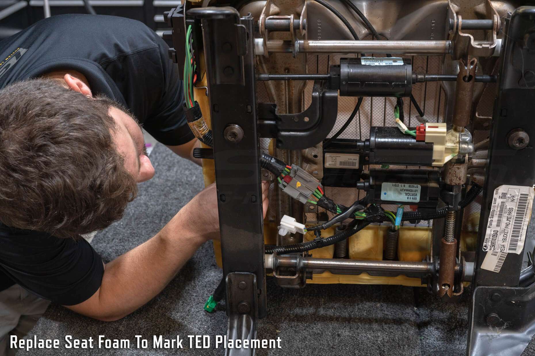
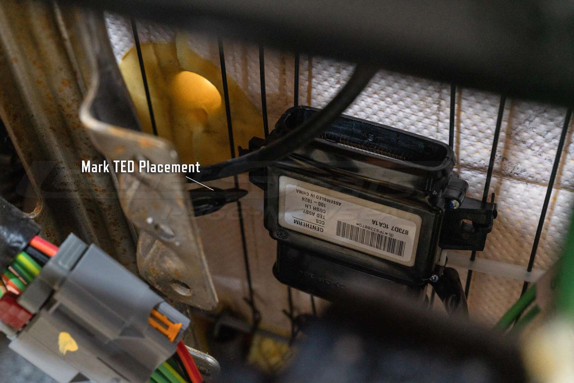
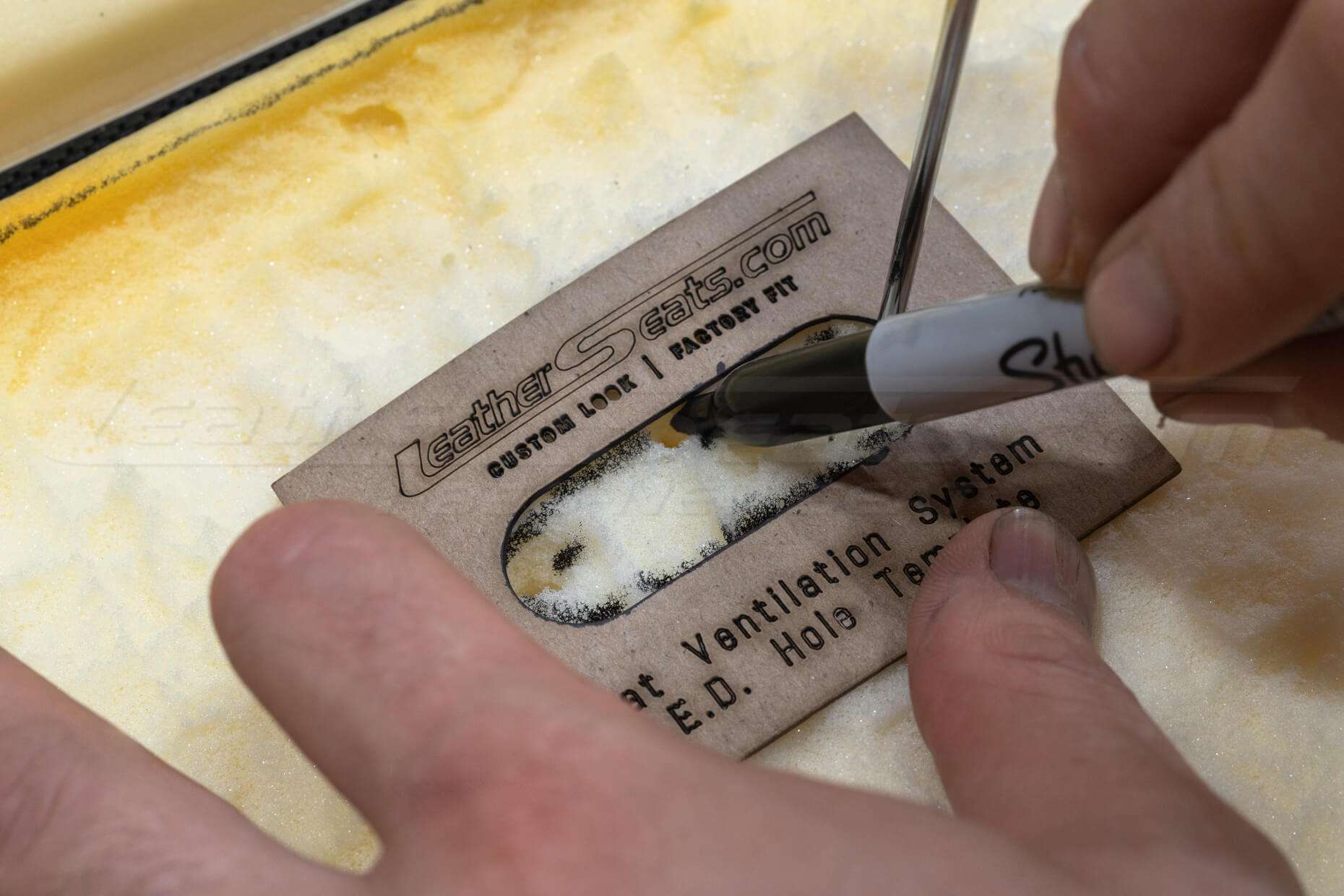
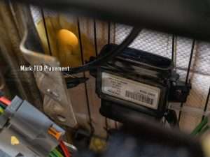
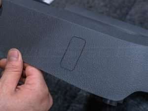
Temporarily attach the TED unit to the back/bottom of the seat, put seat foam back in place, and mark where the TED unit will connect.
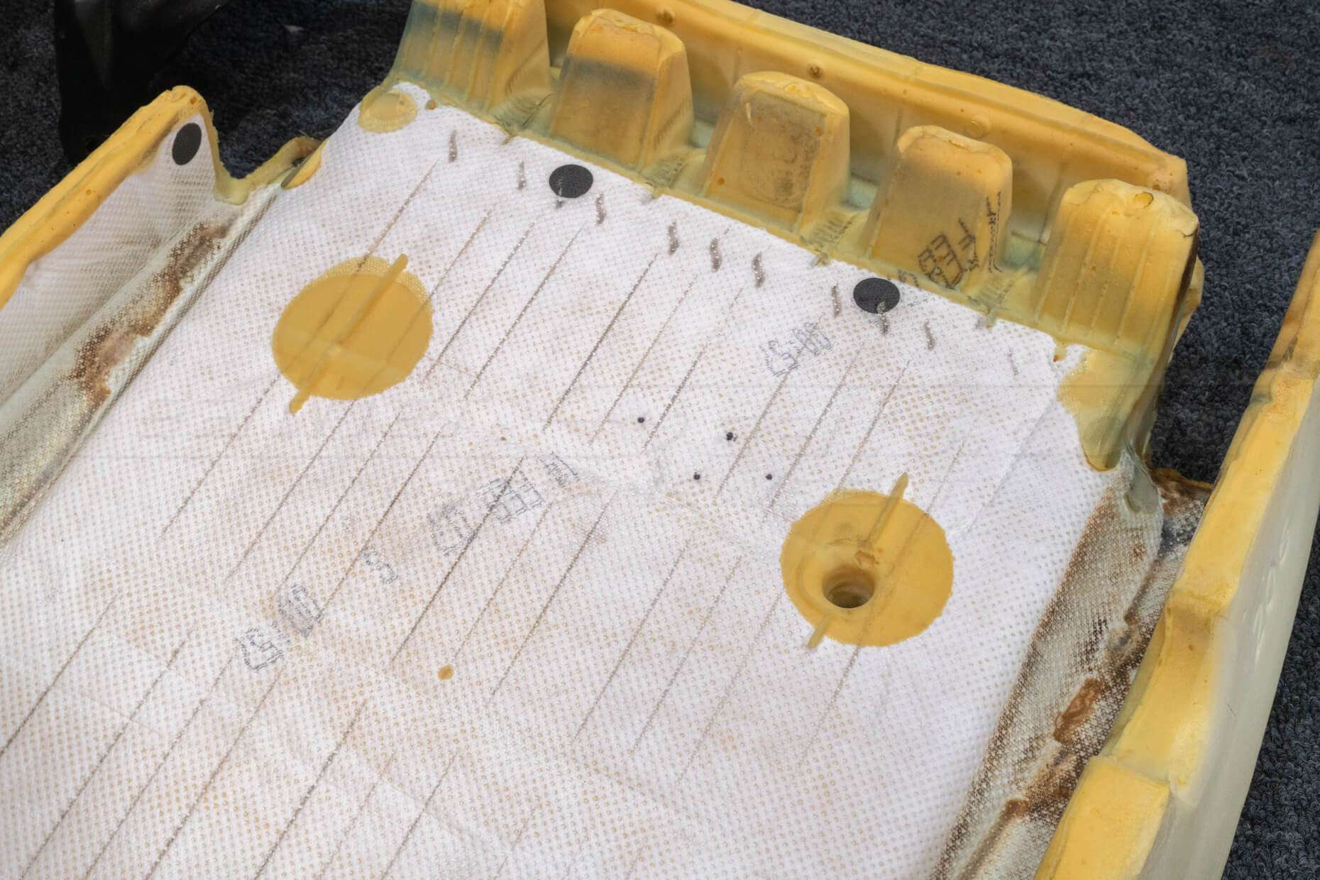
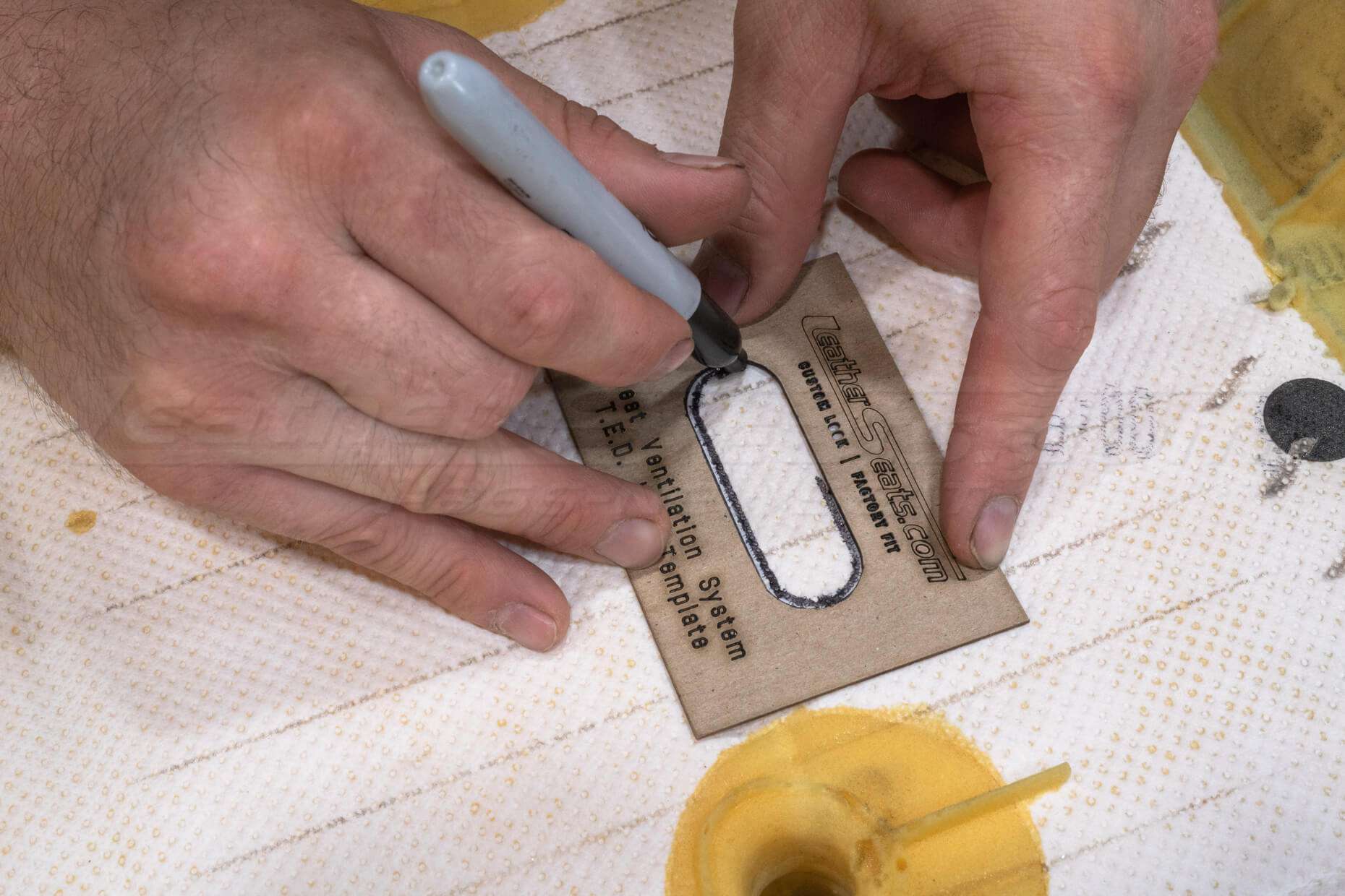
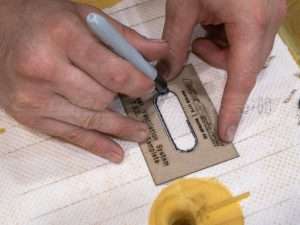
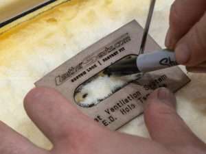
Use the TED hole template to trace the outline of the TED output on the seat foam.
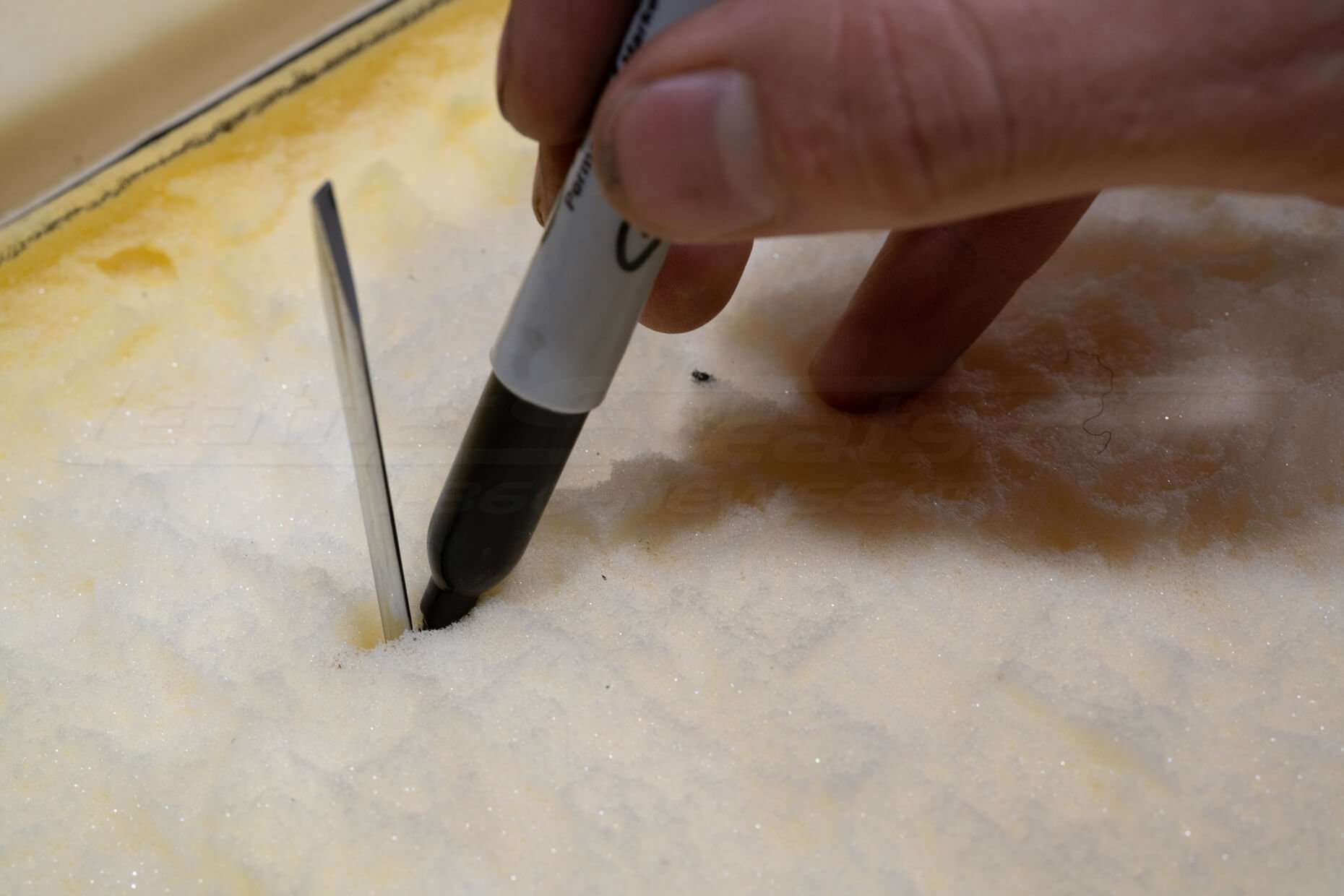
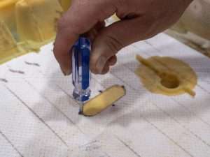
Use a guide, such as a screwdriver, to determine where to trace the second outline on the opposite side of the seat foam.
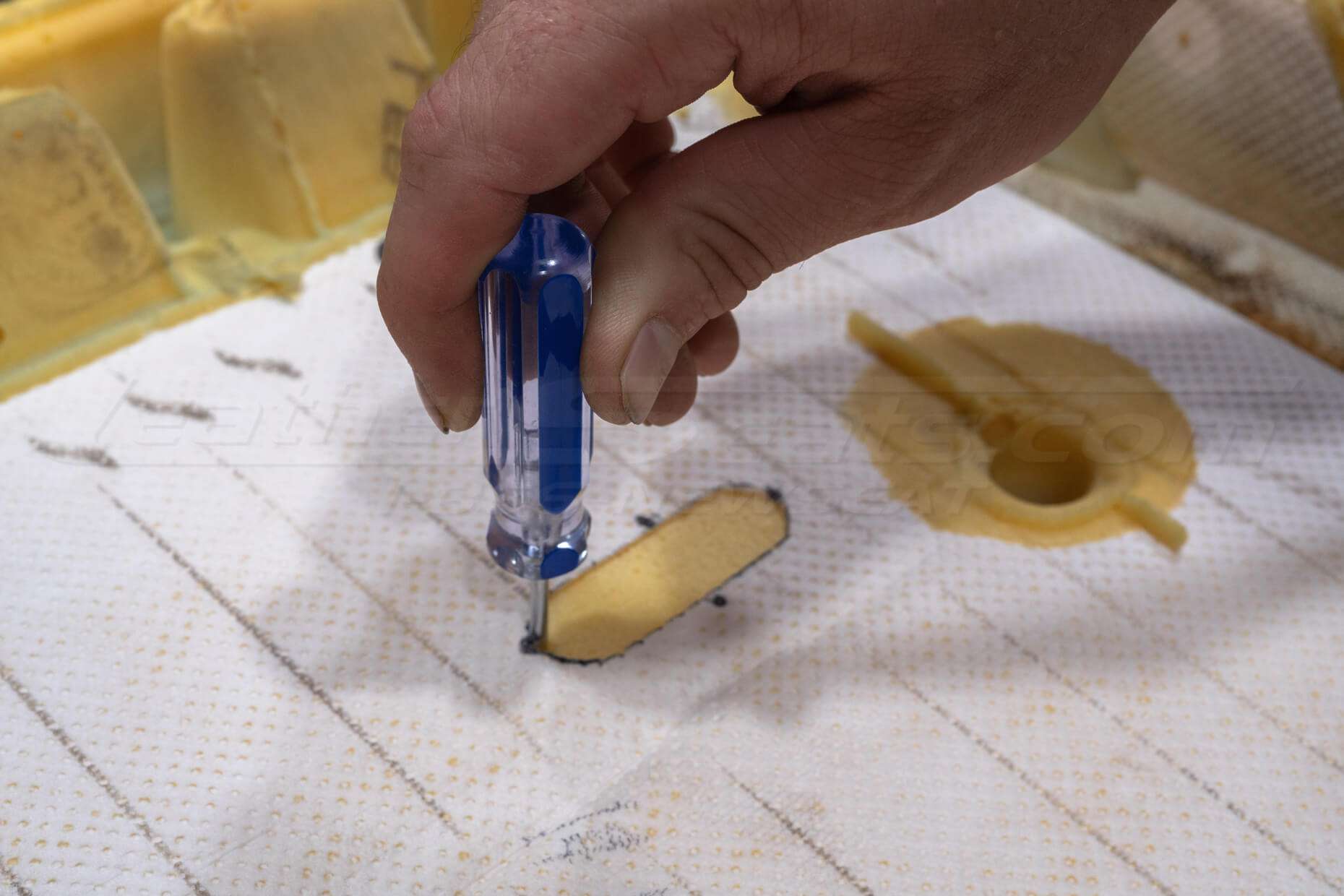
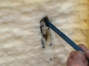
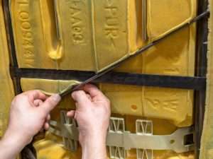
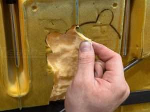
Cut Hole For TED Output
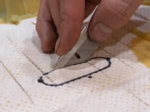
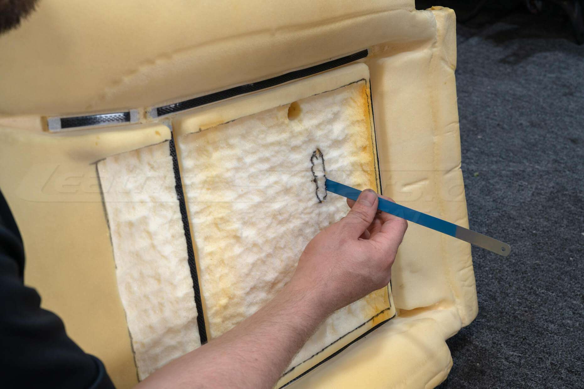
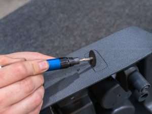
Use a razor blade to start an initial cut on the outline. Make sure that this cut is perpendicular to the surface of the foam to ensure a straight and aligned hole through the foam.
Use a longer blade to then cut the shape of the outline all of the way through the foam.
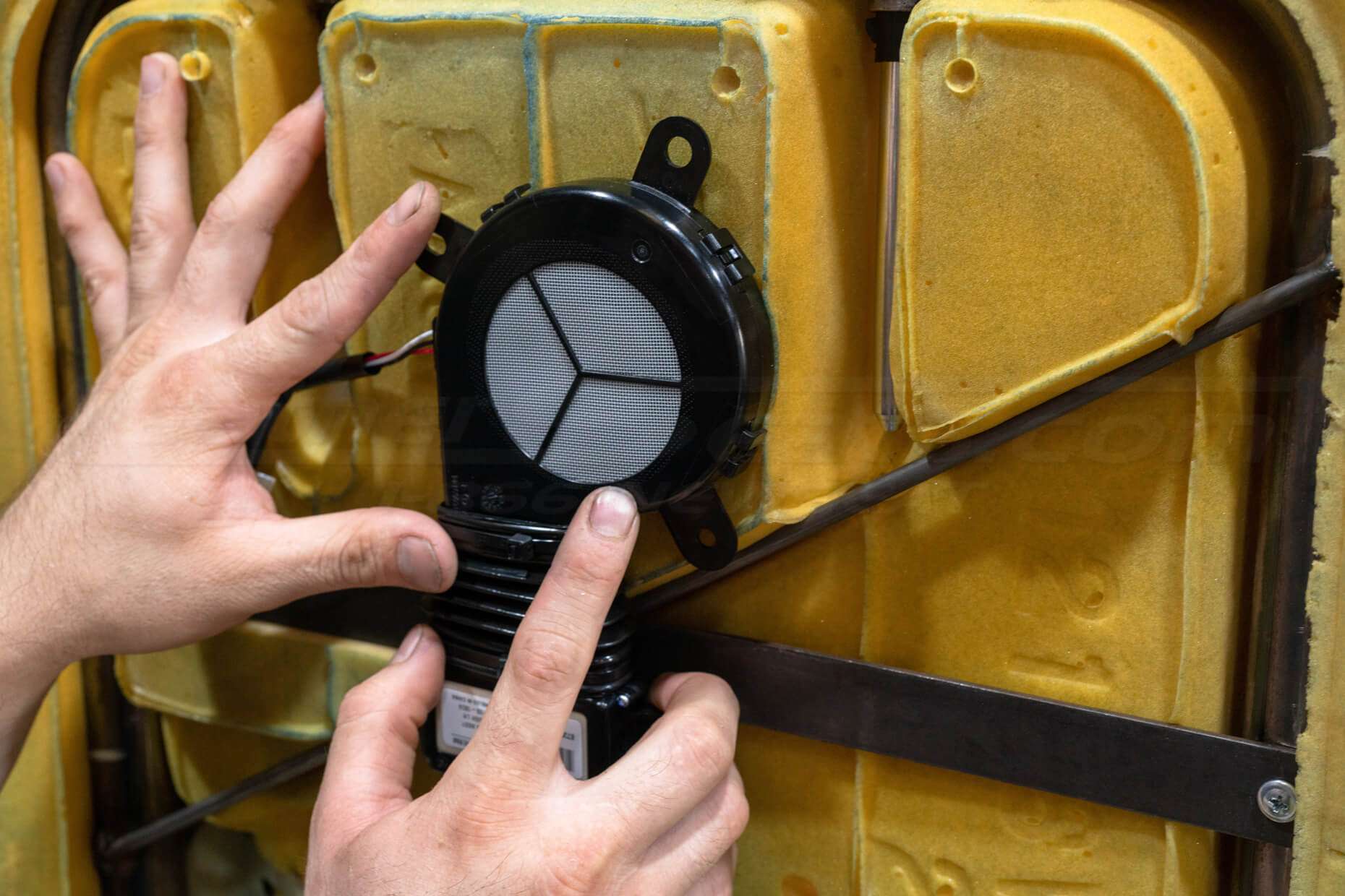
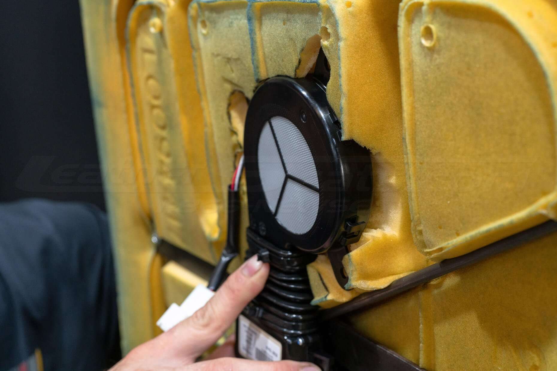
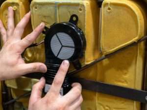
Attach/Mount TED and Blower
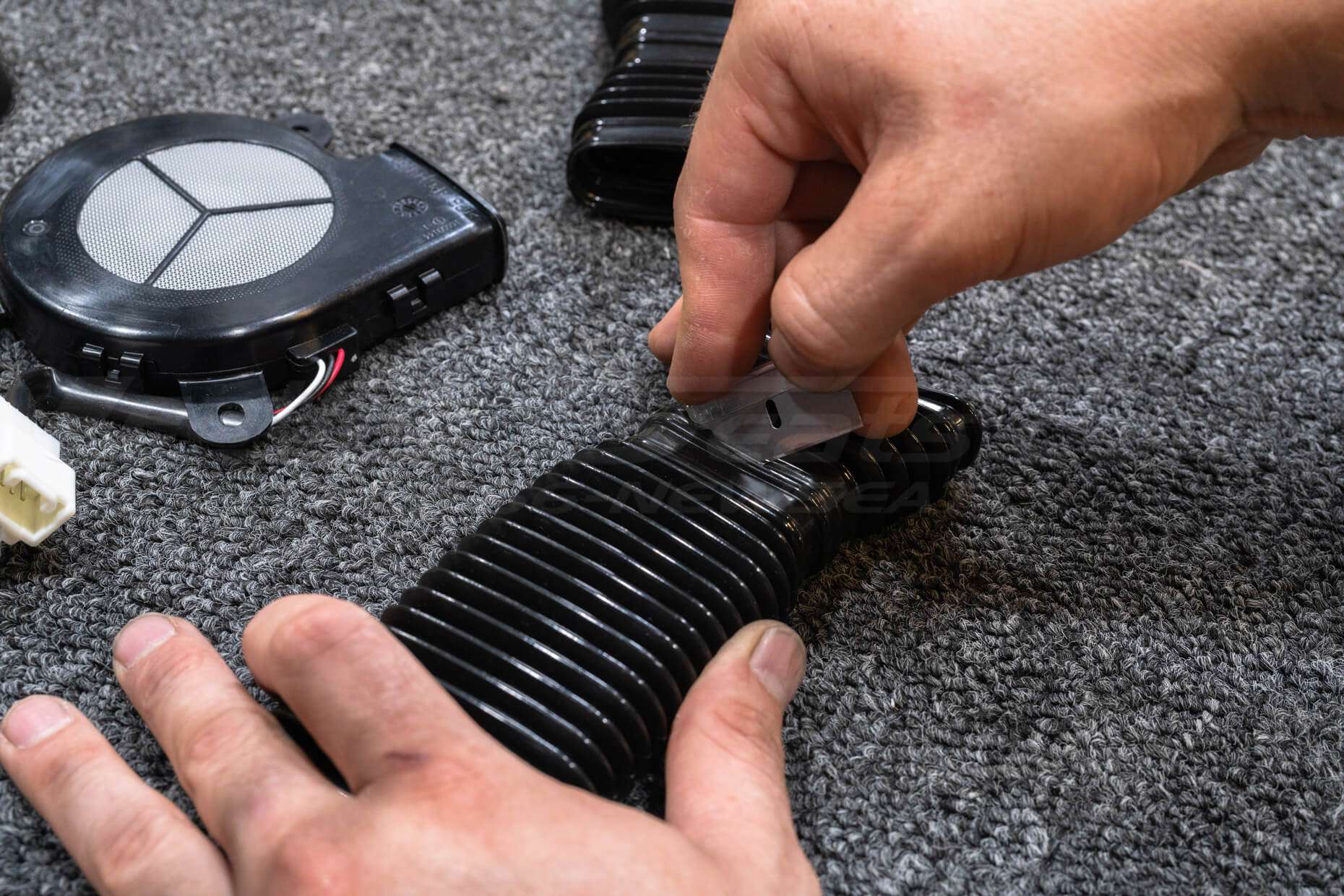
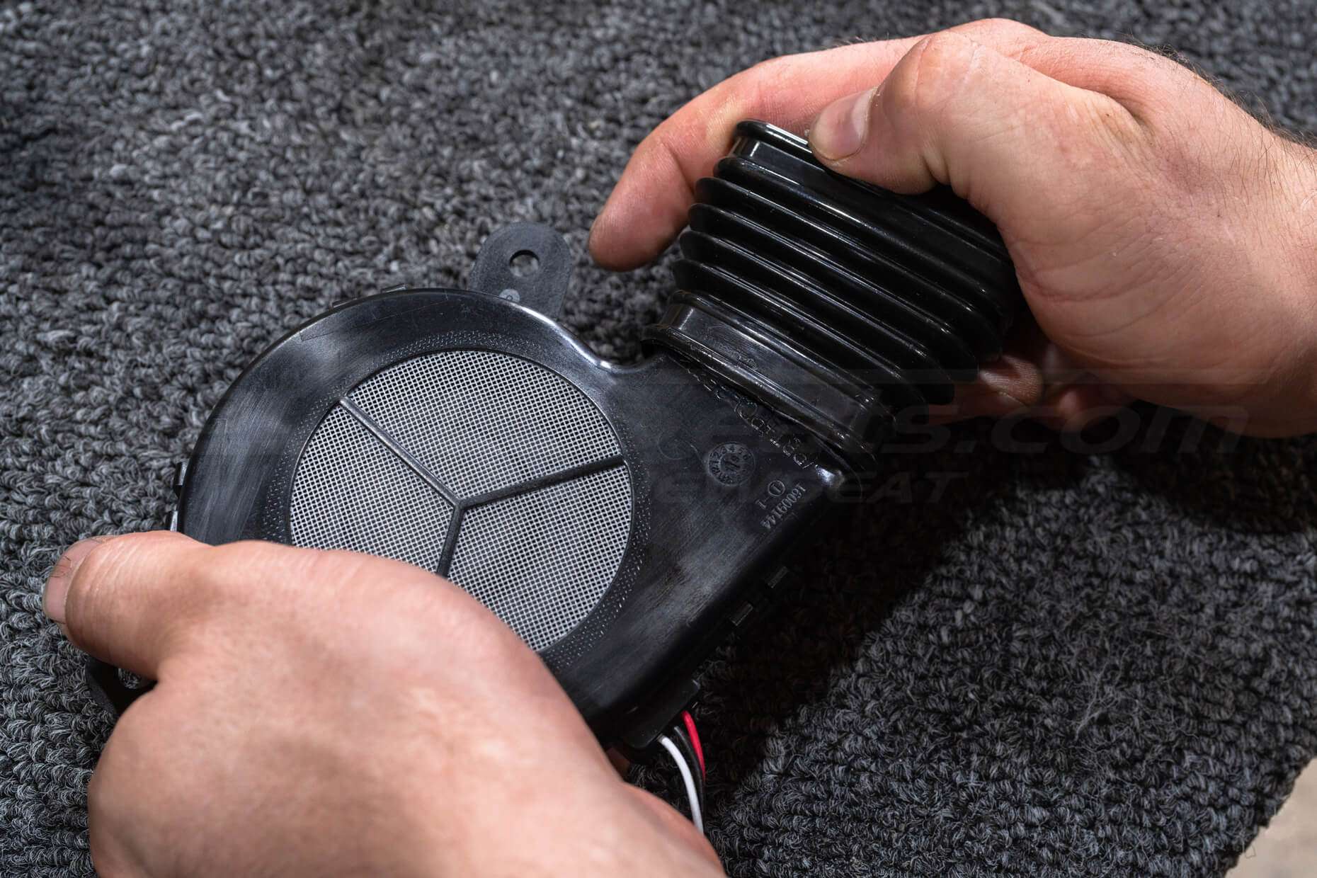
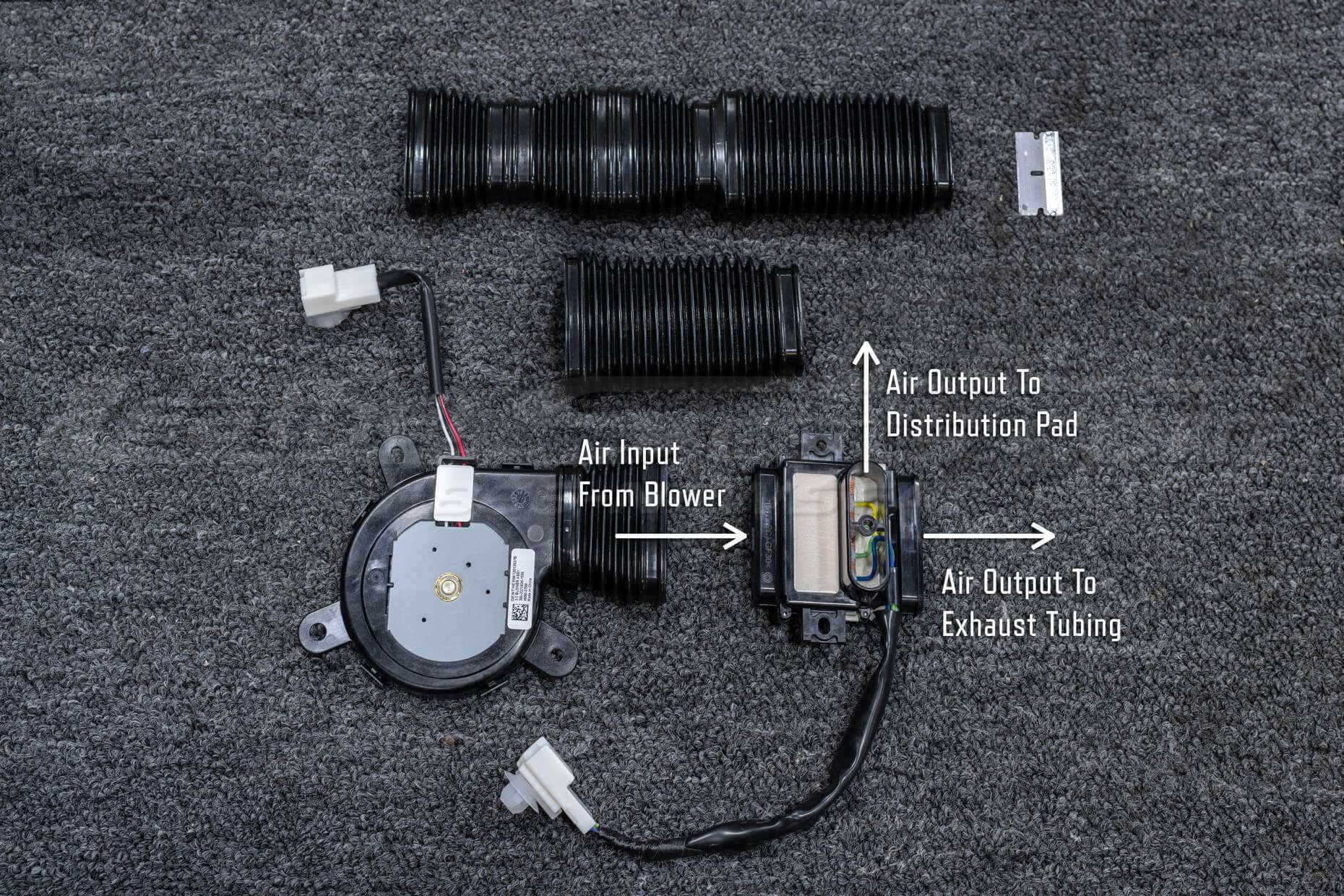

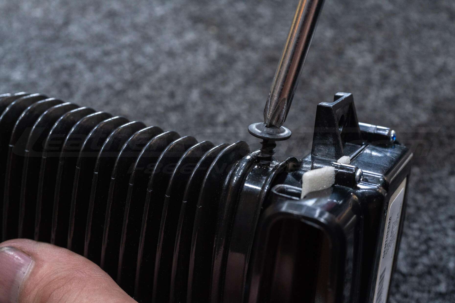
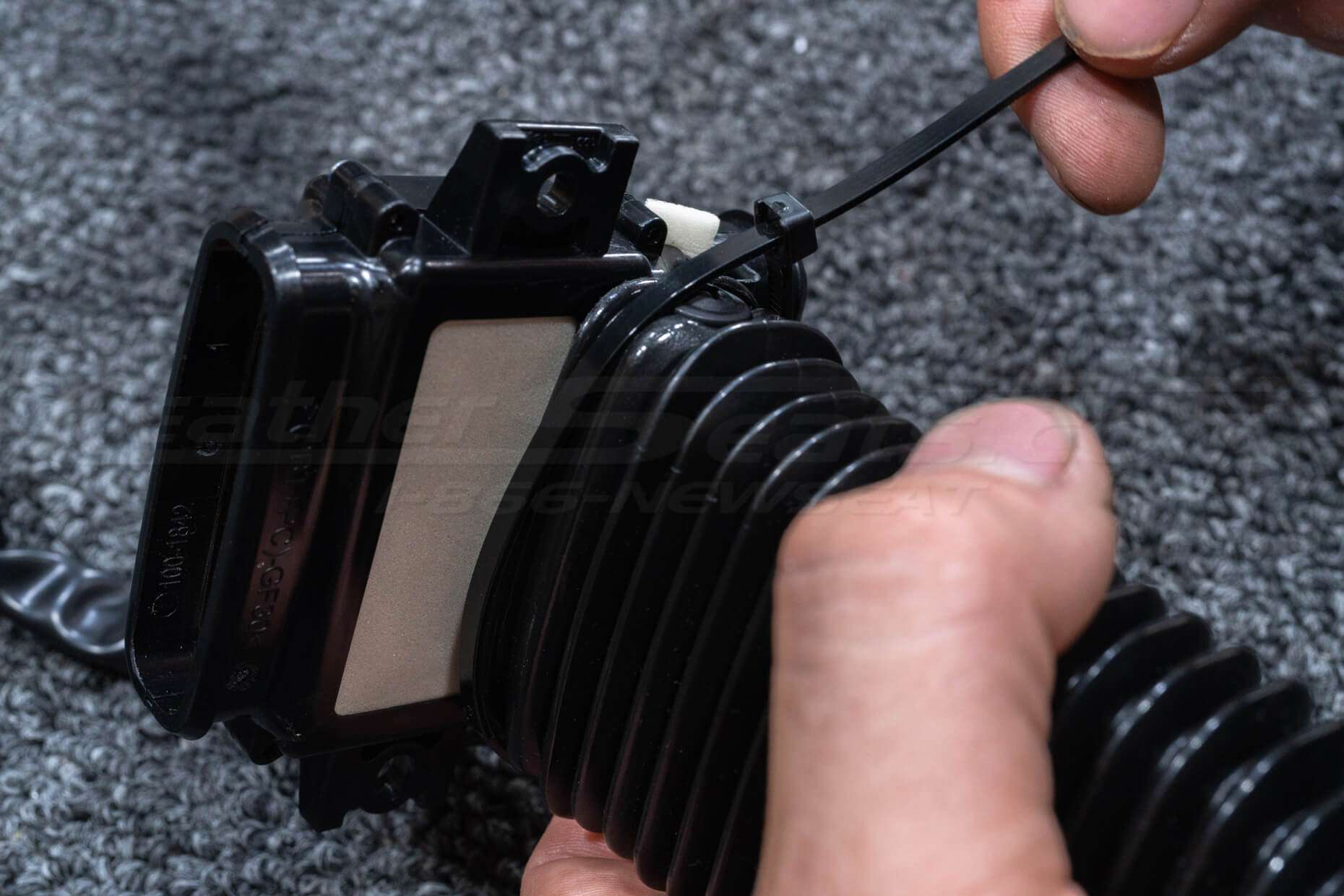
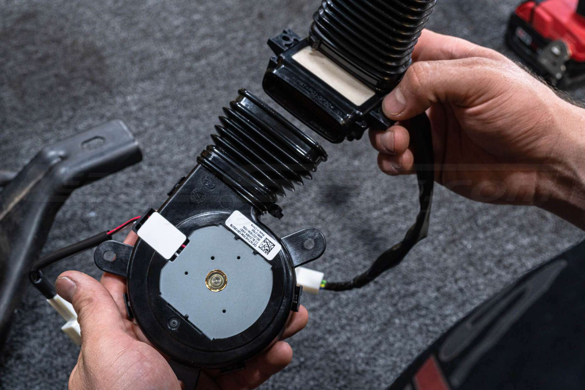
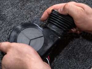
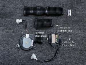
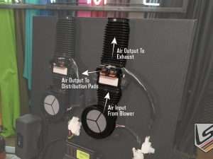
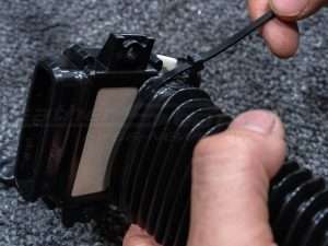
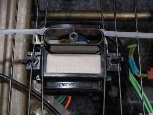
Orient the TED Unit and centrifugal blower according to the photo for correct airflow.
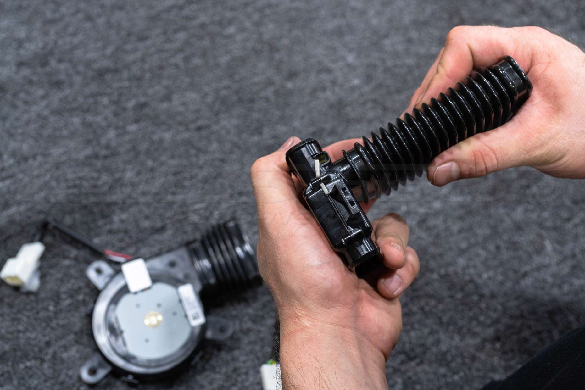
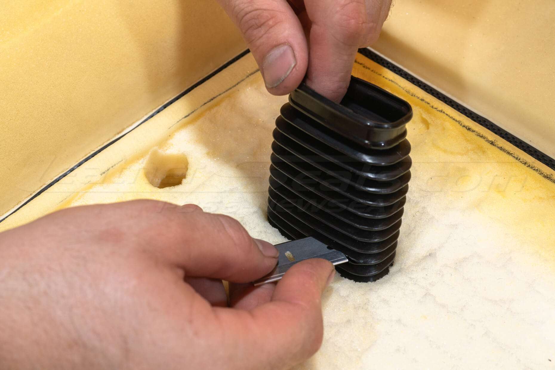
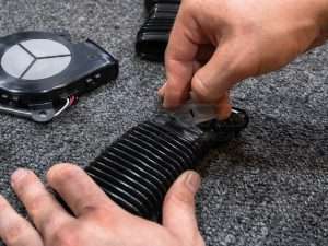
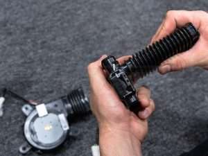
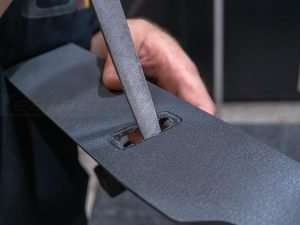
Trim a short piece of duct tubing to connect the TED unit and blower and attach a longer piece of tubing to the TED’s output that will pass through the seat foam. For the output, we recommend using stinger screws and/or zip ties to secure these attachment points.
Mount this assembly to the seat, feed the TED output tubing through the foam, and trim the excess duct tubing to be flush to the surface of the foam.
Mounting the TED/Blower assembly may require some fabrication or modification to the seat, as not every seat will have secure points for attachment in that location.
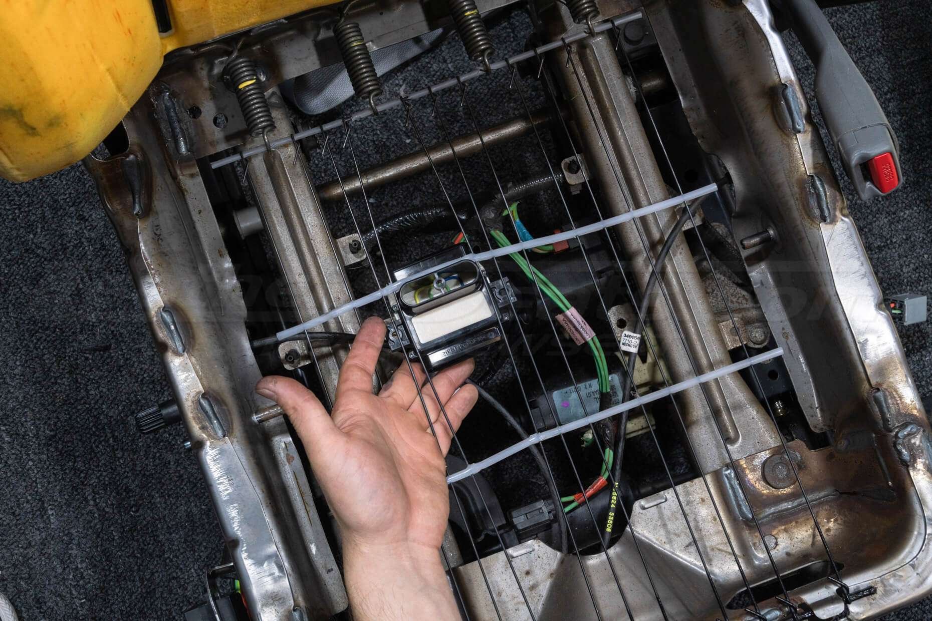
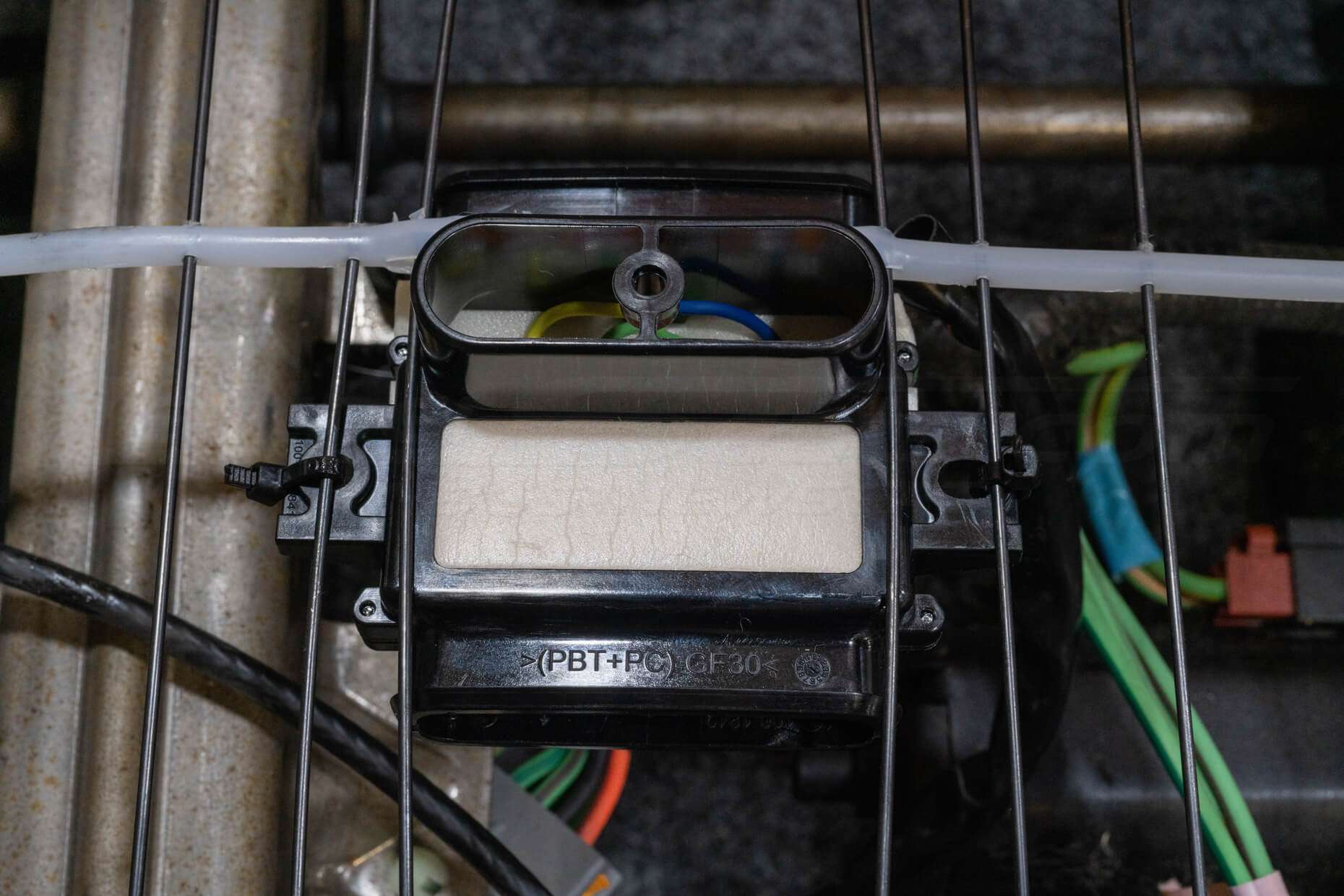
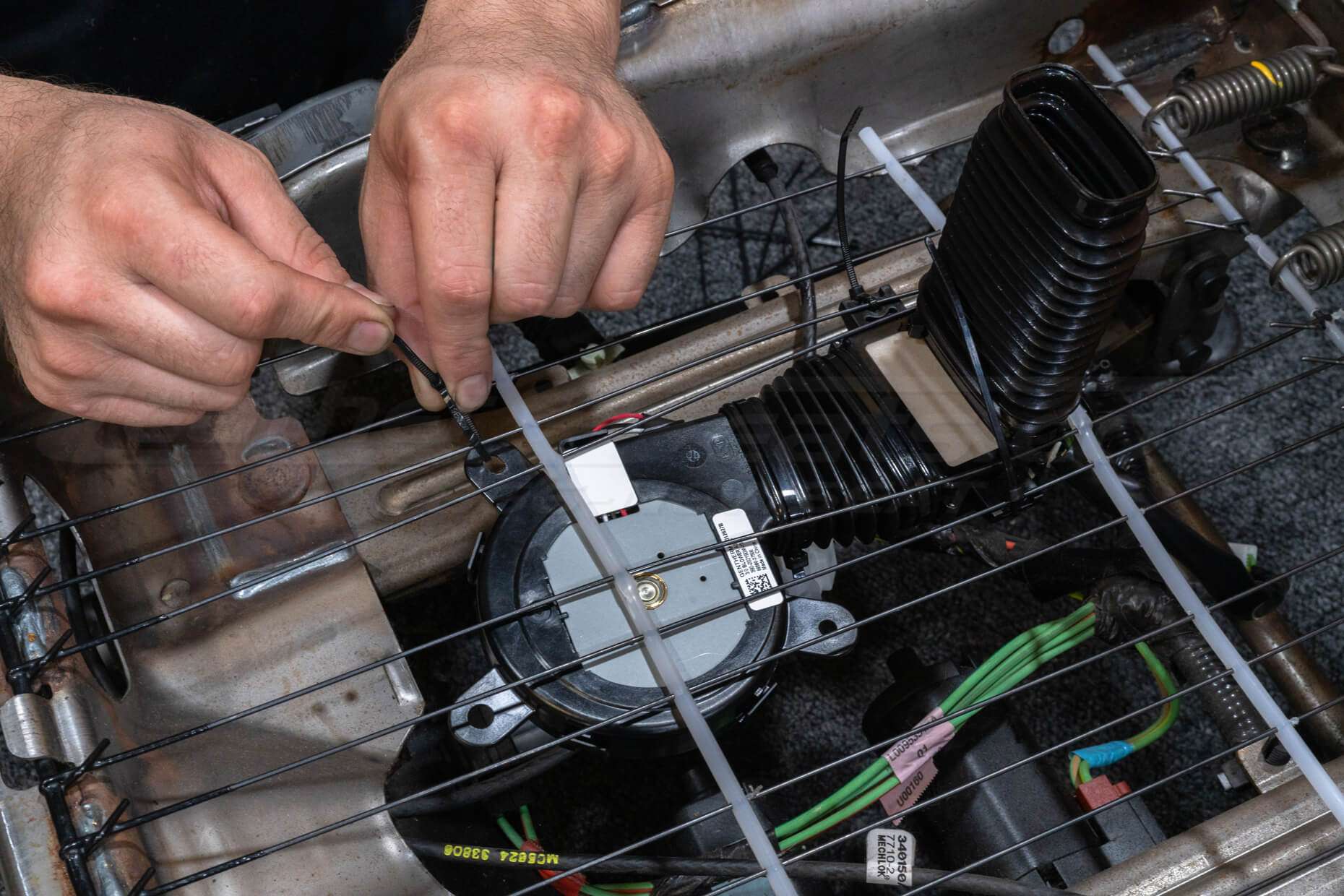
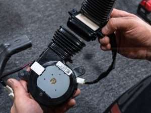
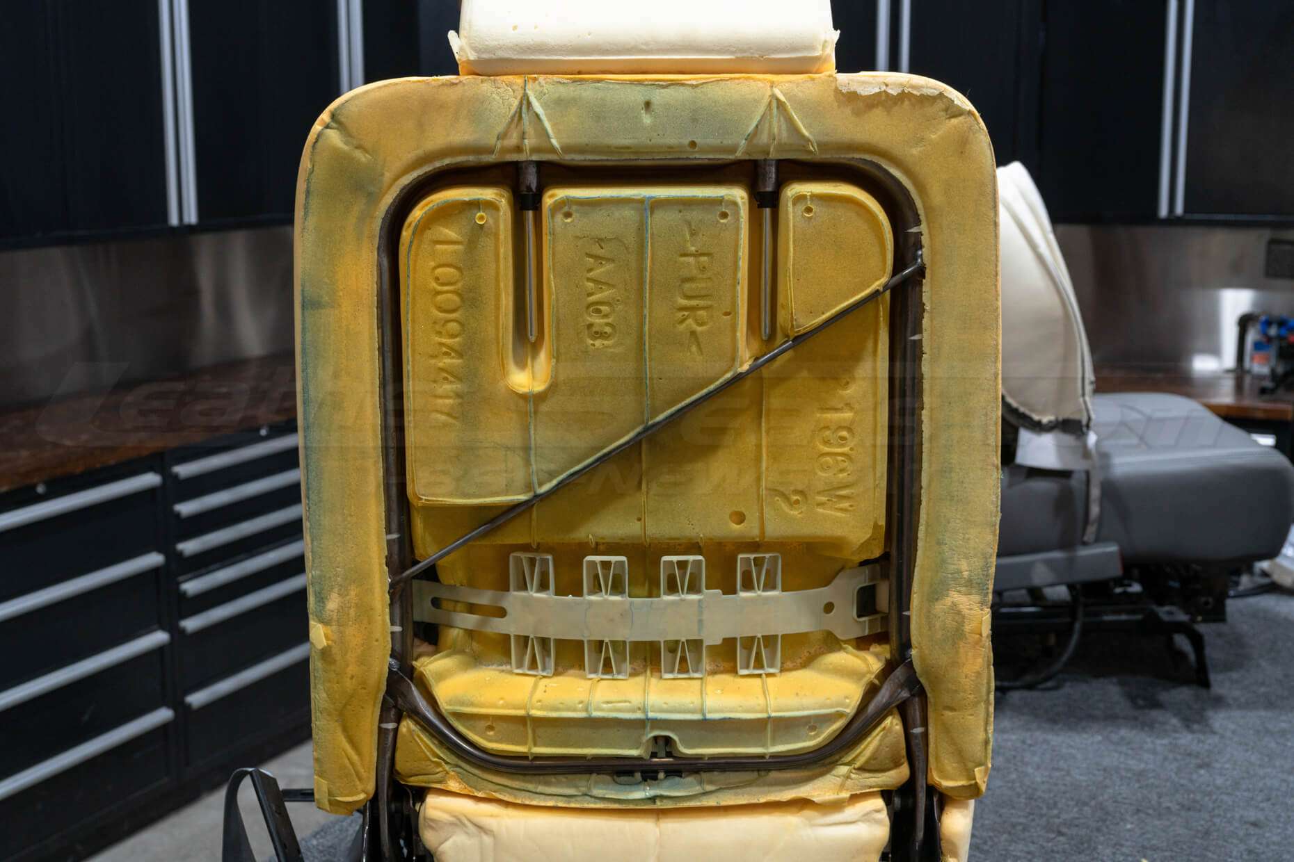
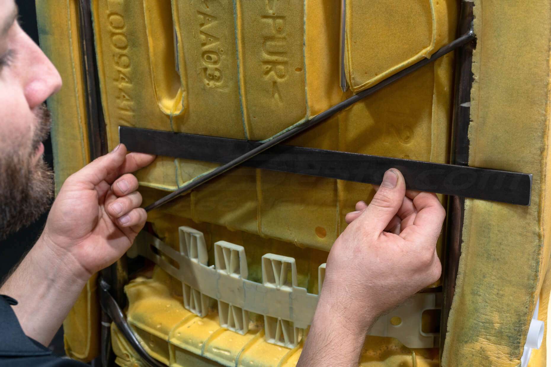
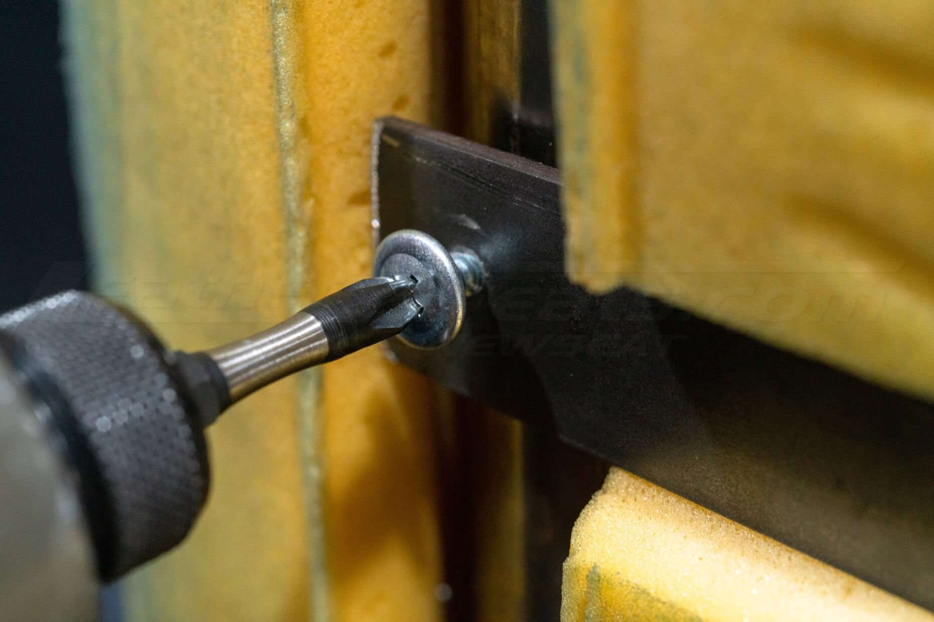
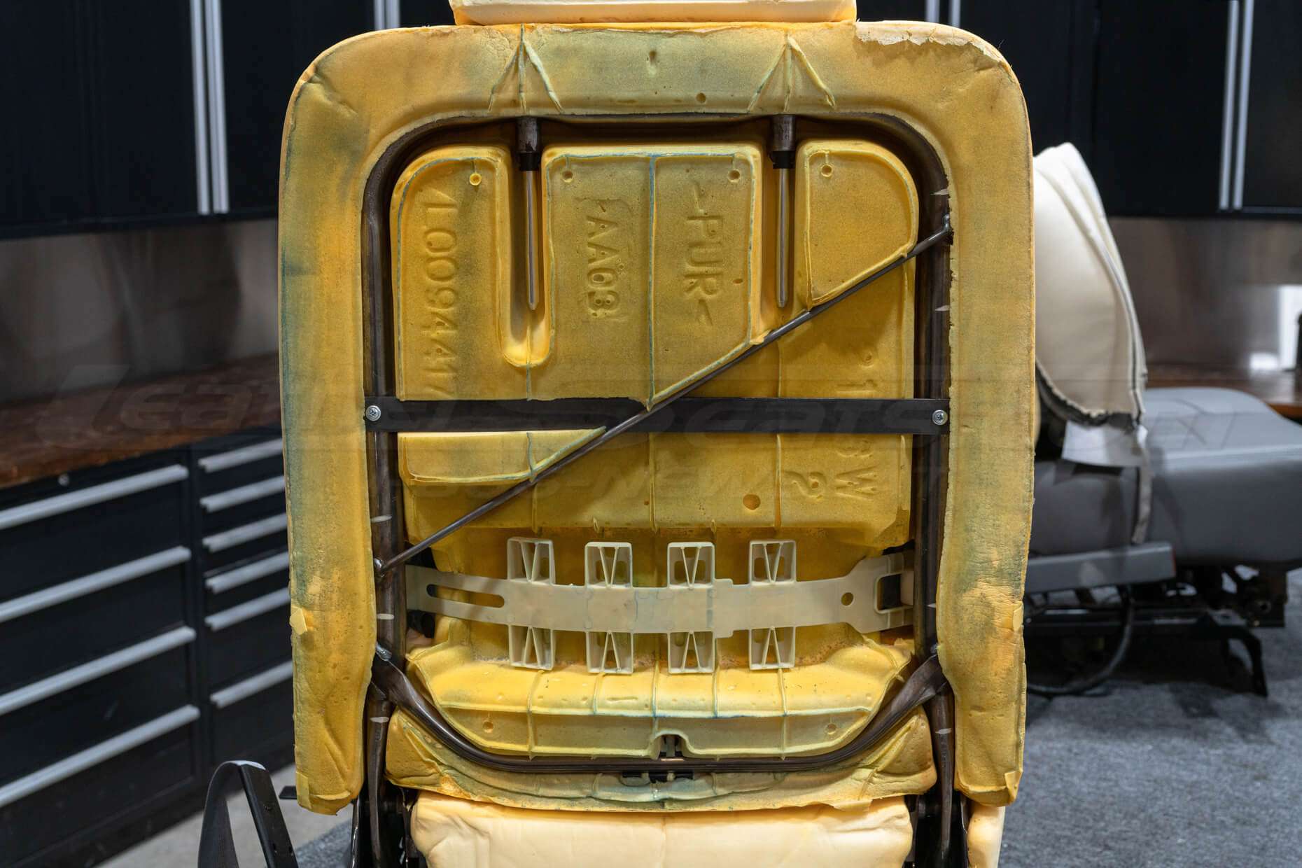
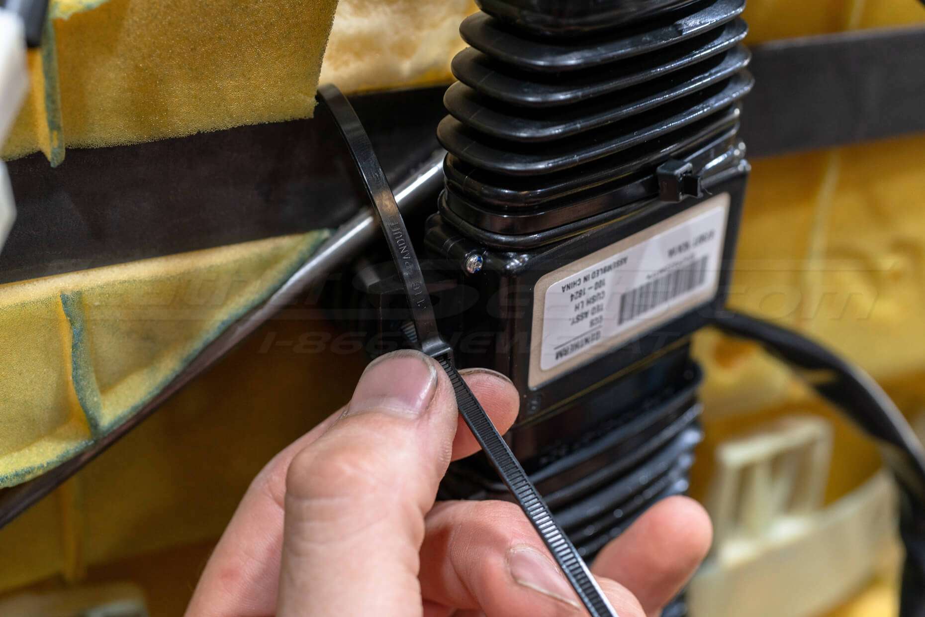
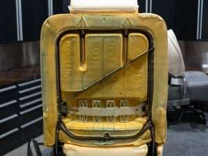
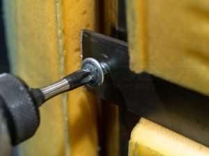
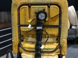
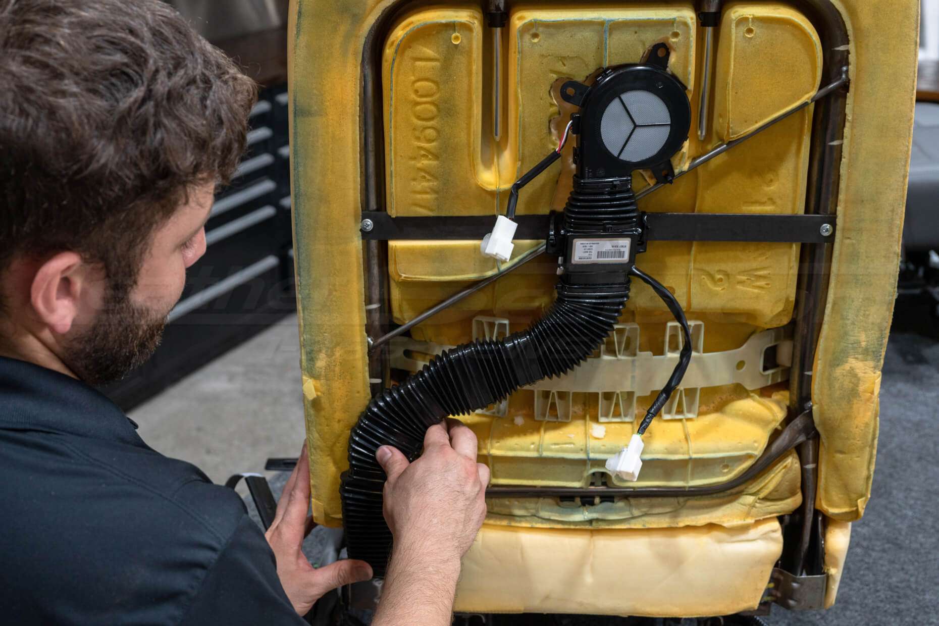
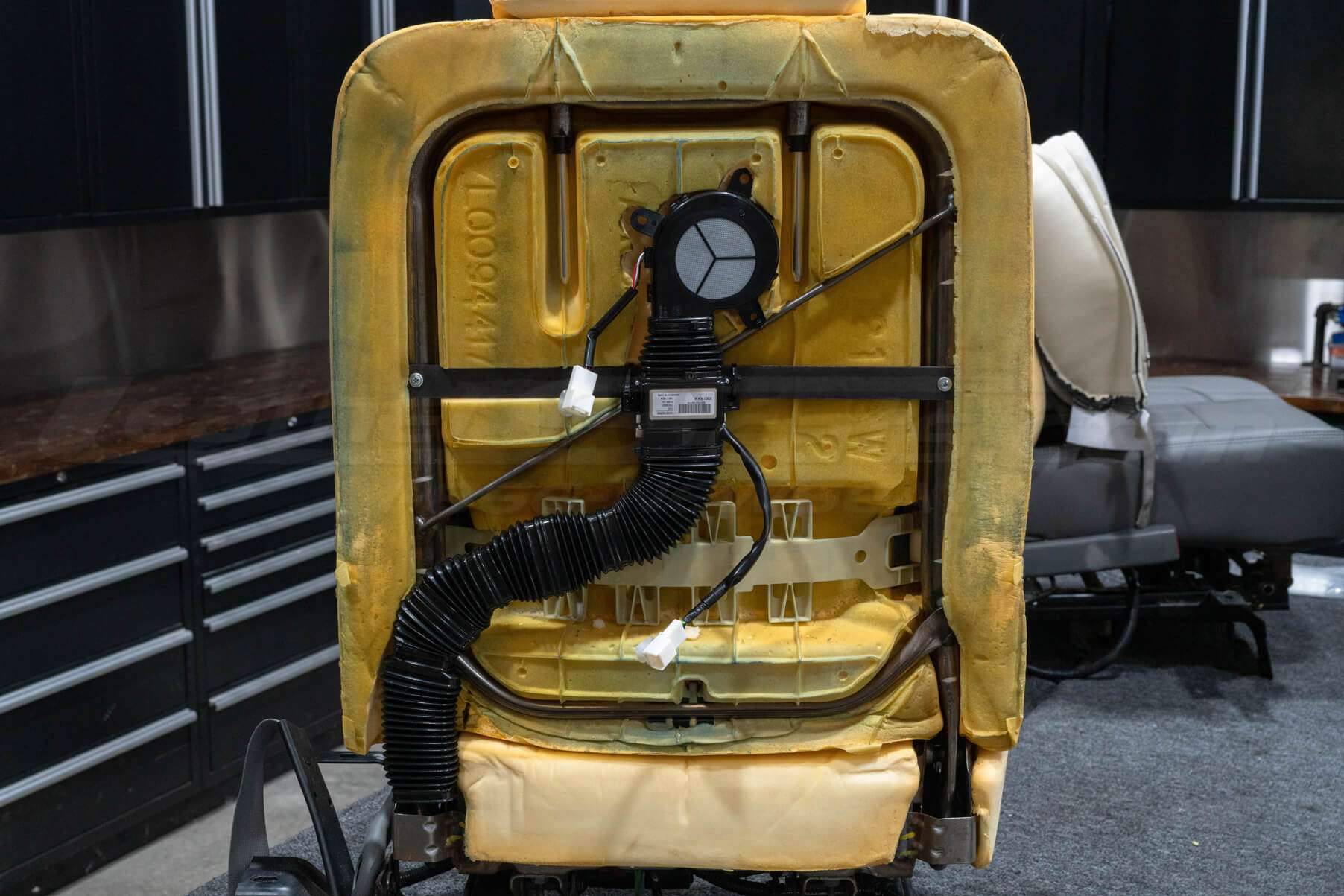
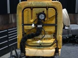
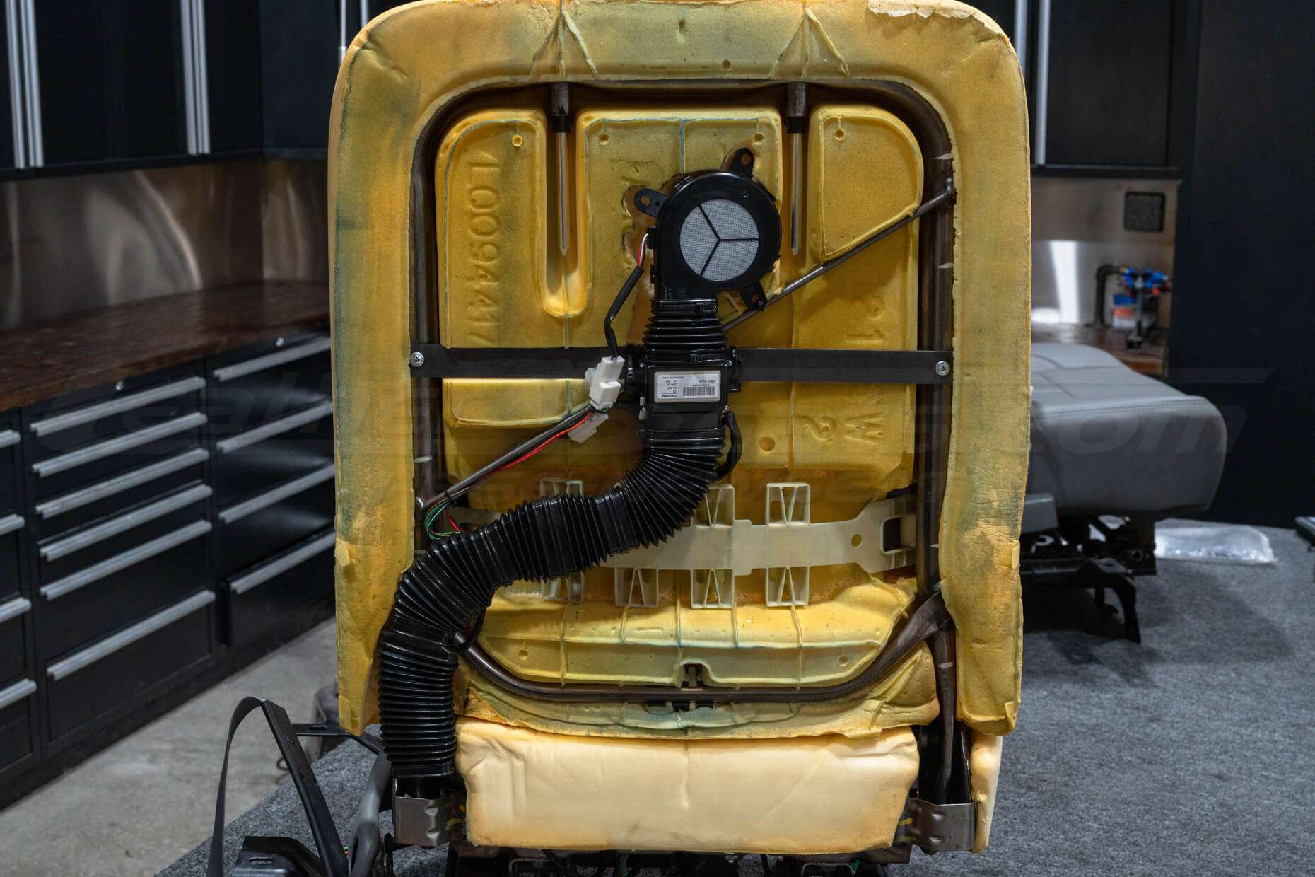
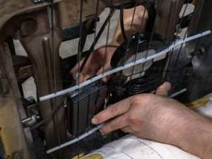
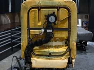
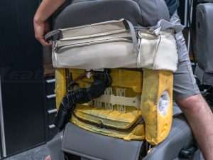
Modify Seat (As Needed)
Some seat components may need to be modified to mount the TED and blower assembly. In this example, we modified the seat foam and added an additional bracket to the seat frame to mount the TED and blower assembly flush with the seatback.
Every seat will be different and it will be up to you to figure out the best mounting method for your vehicle. You may need to get creative and potentially fabricate your own mounting points as seen here in the photos.

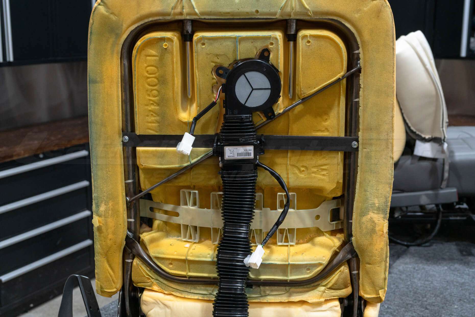
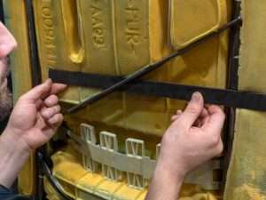
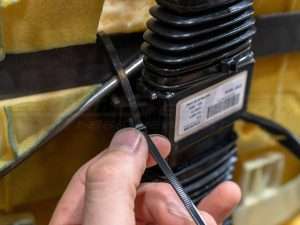
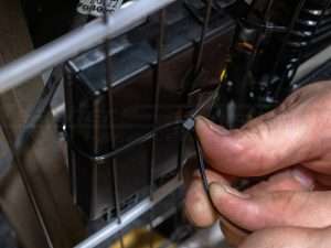
Determine Exhaust Path
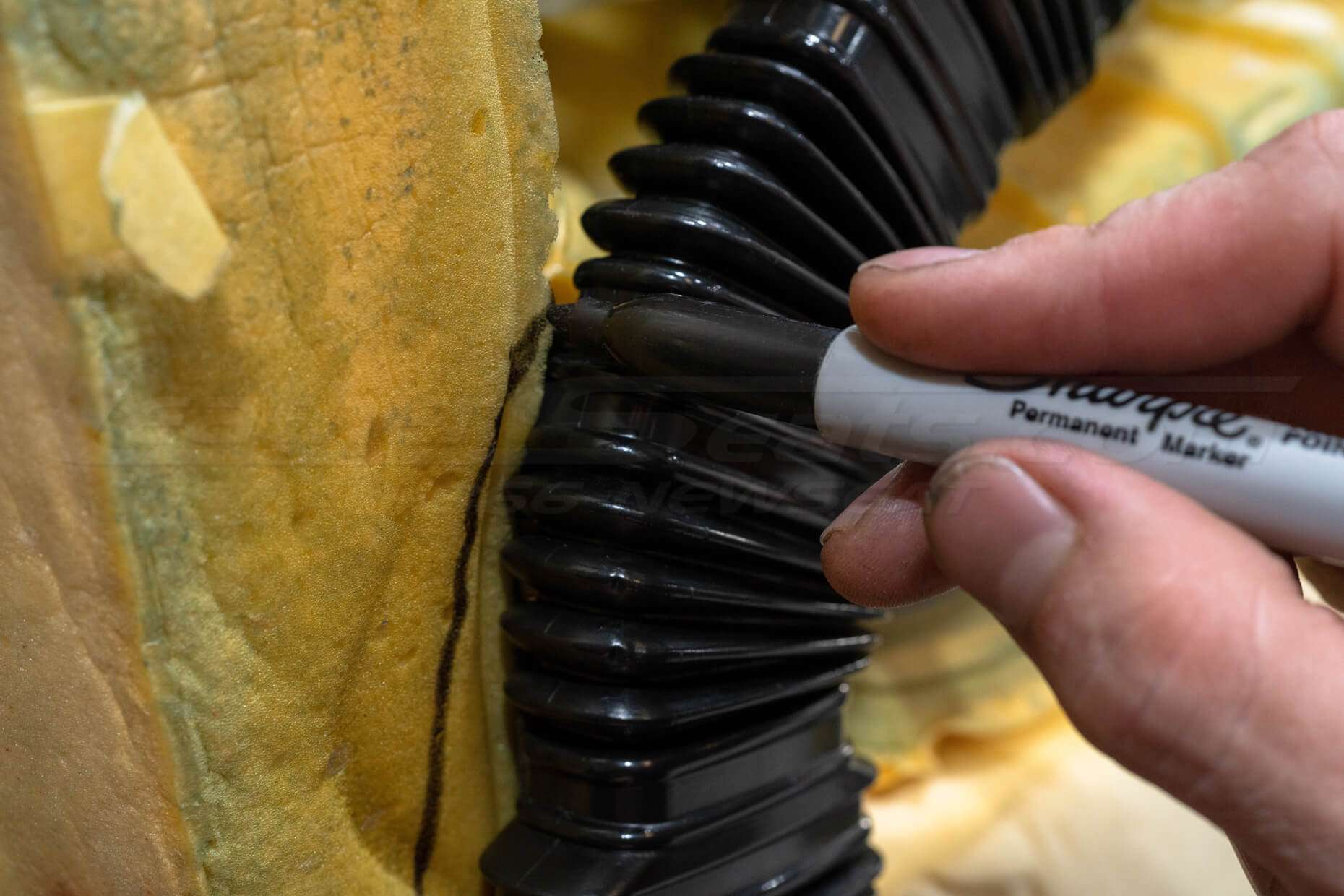
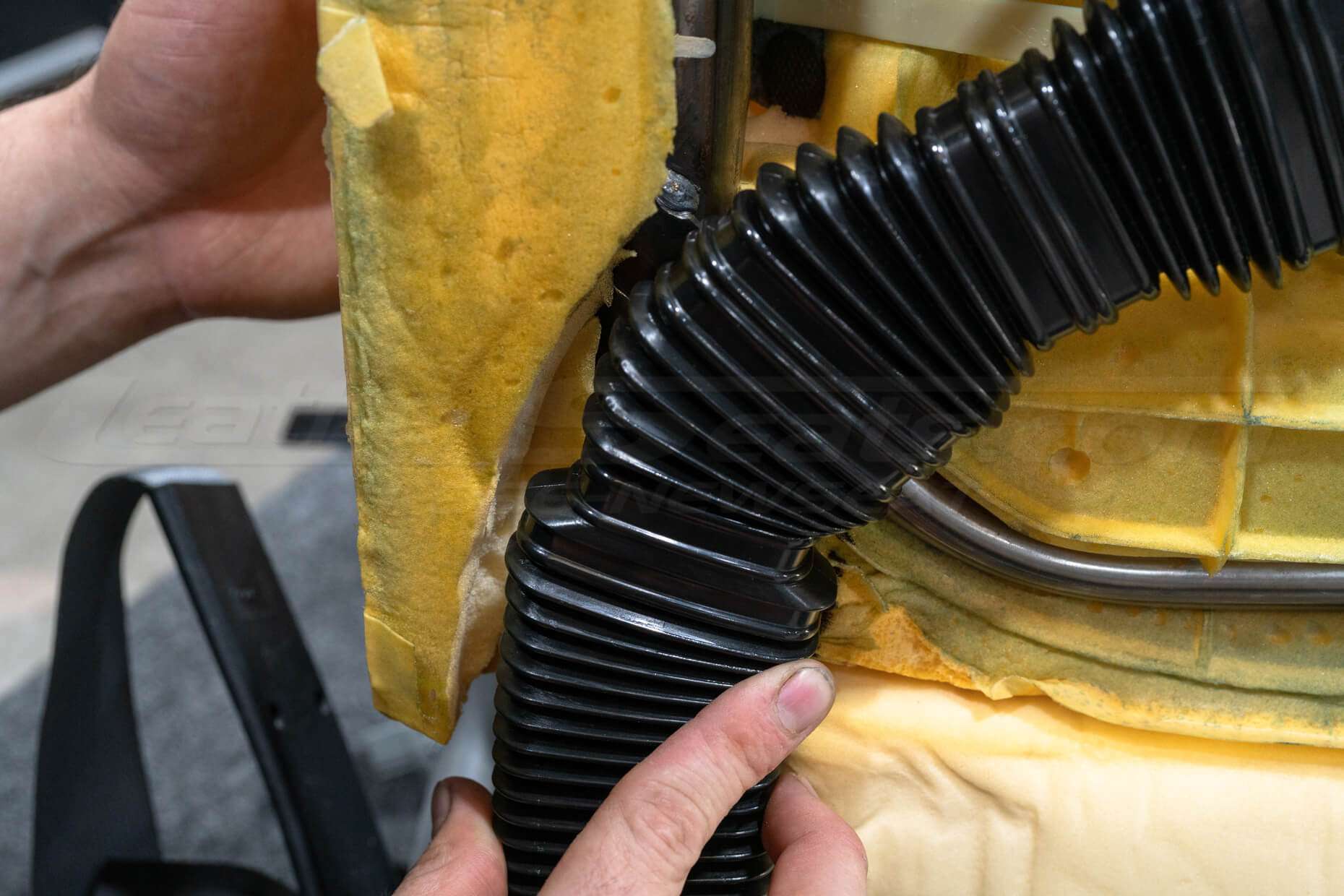
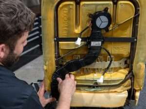
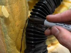
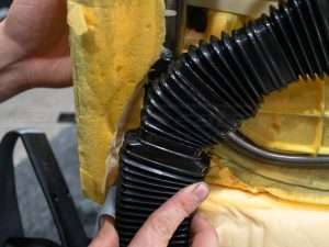
Use included ducting to route exhaust from the TED unit away from the TED and blower assembly. Additional modifications to the seat may be required.
Keep in mind that how the upholstery is installed on your seat may affect where and how the exhaust tubing path will be directed.
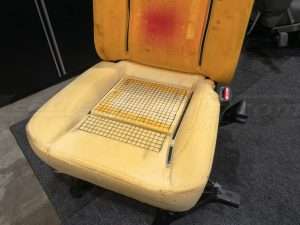
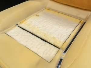
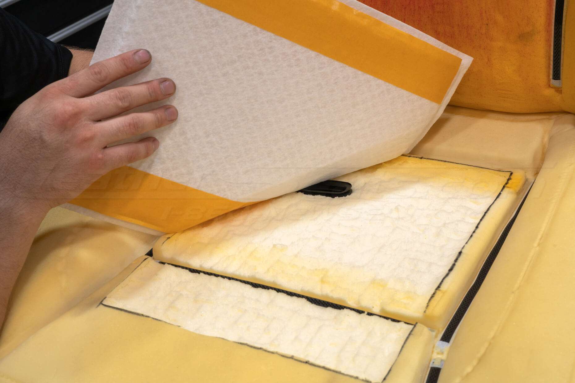
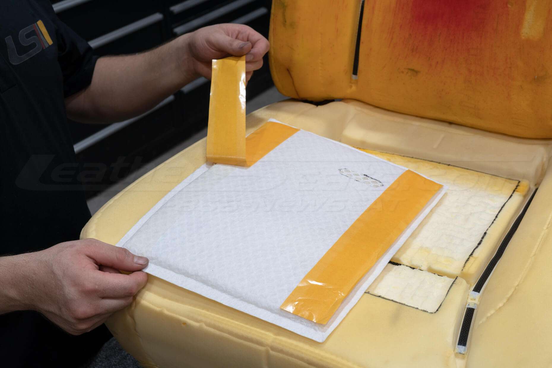
Mount Distribution Pad
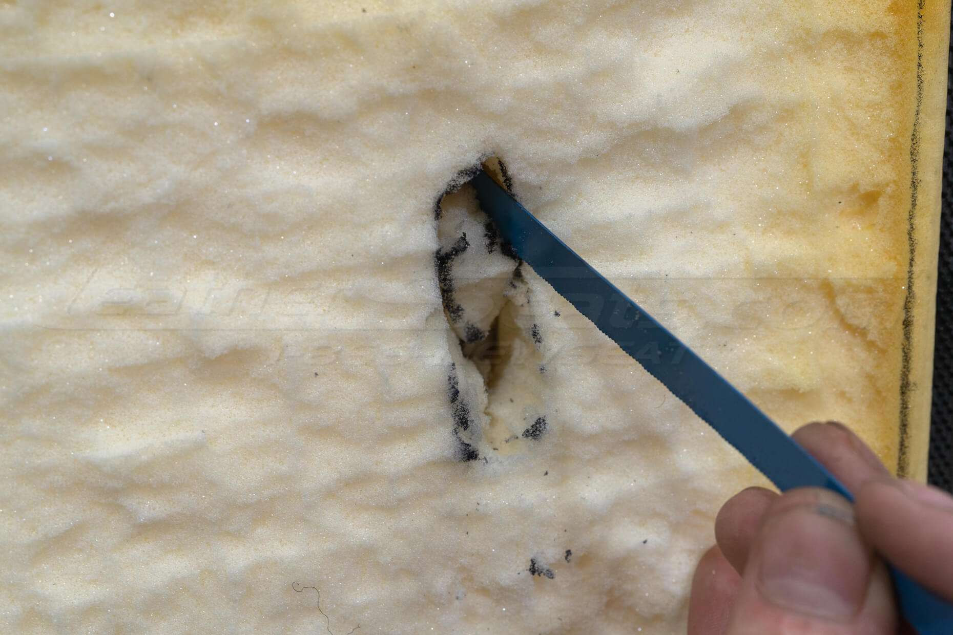
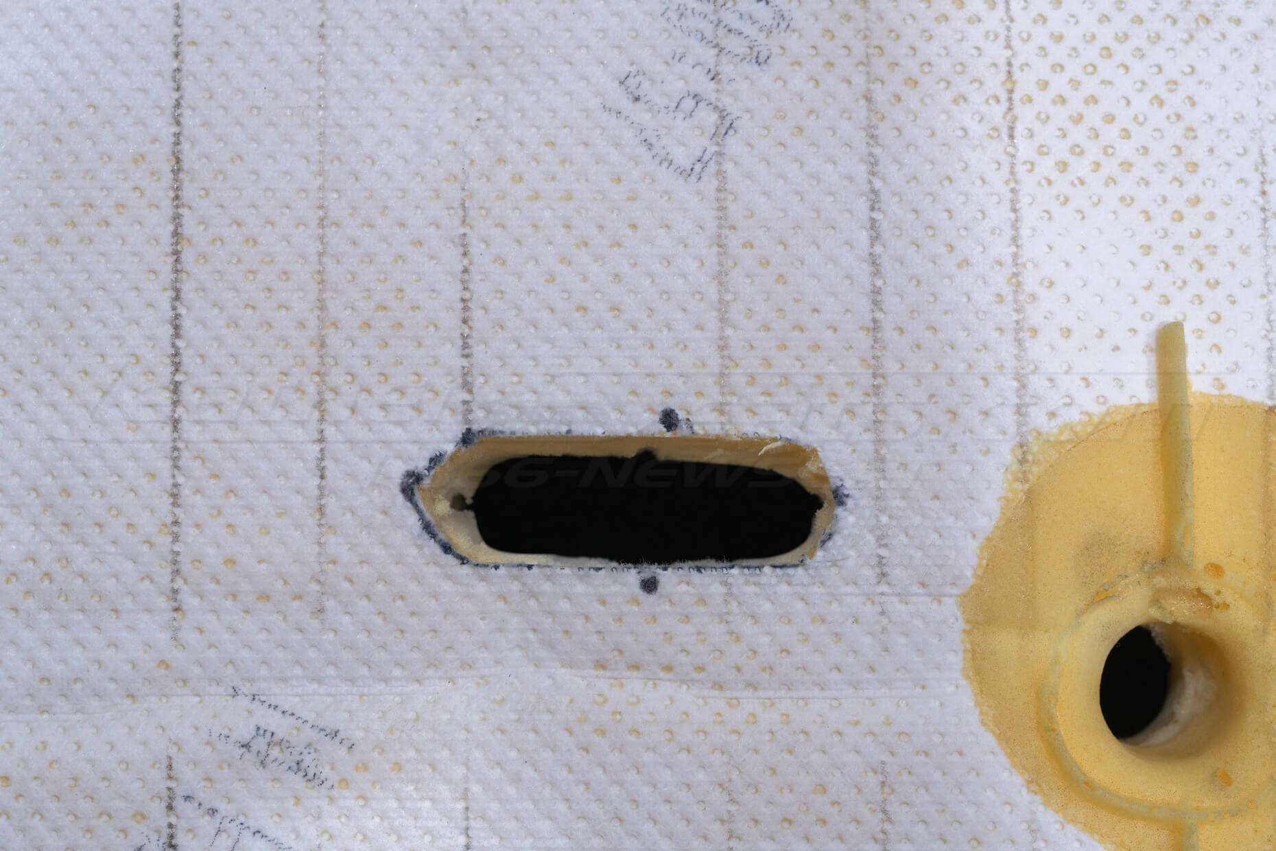
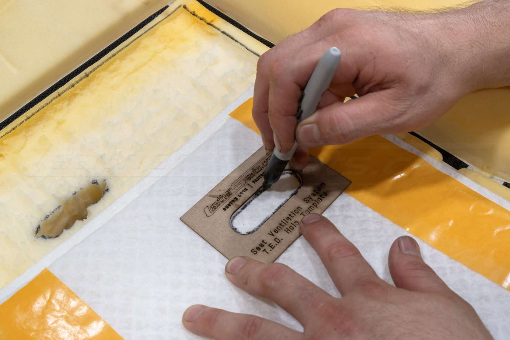
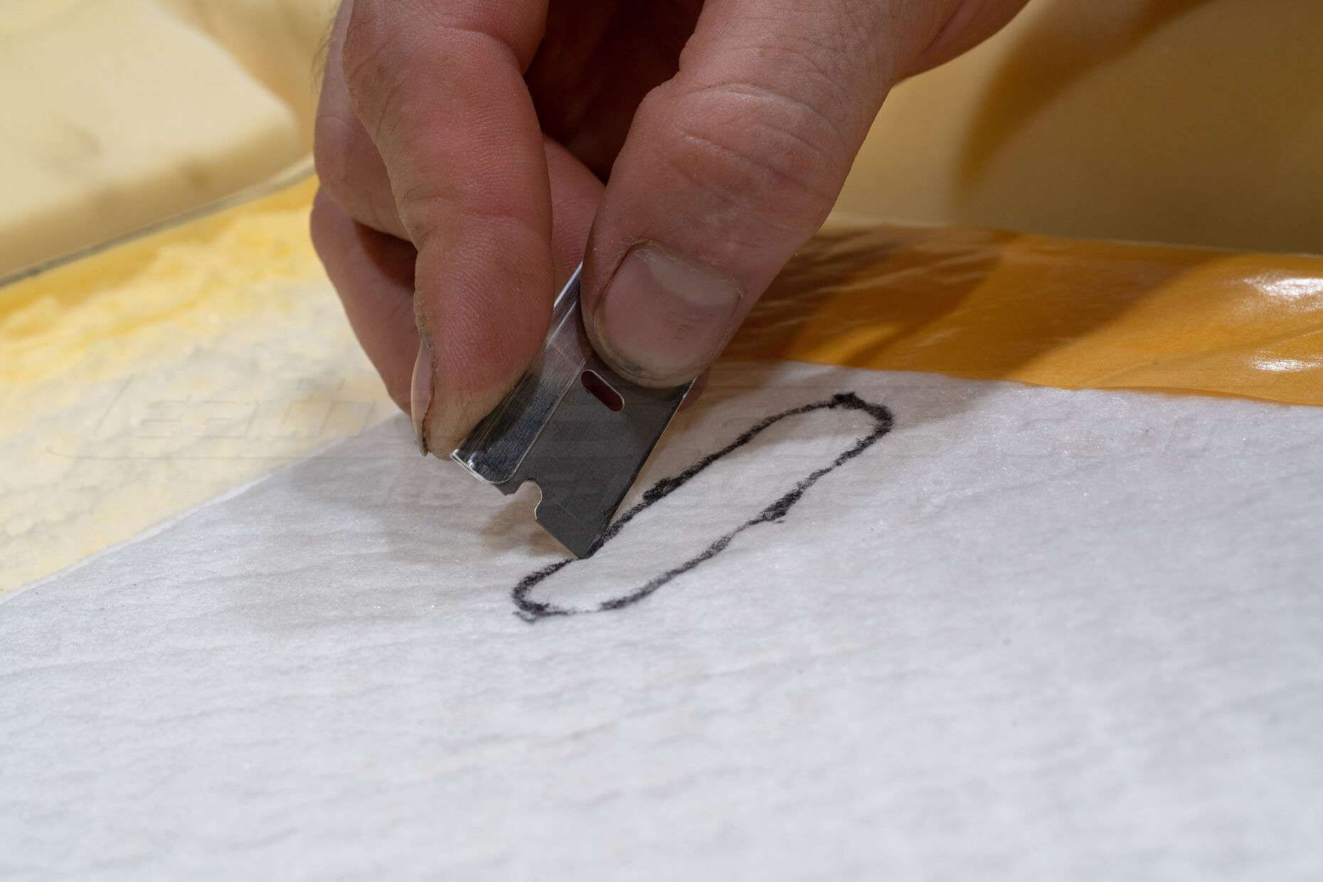
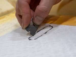
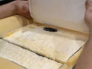
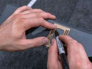
Determine where the TED will attach to the adhesive side of the distribution pad and trace the hole with the provided template.
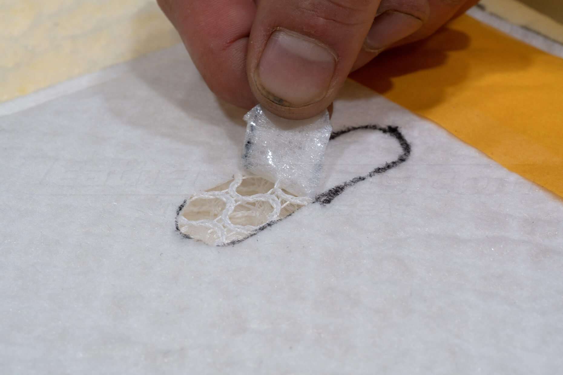
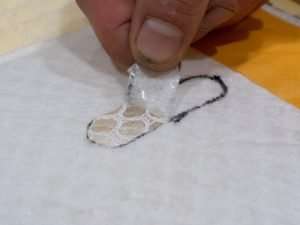
Do not cut all of the way through the distribution pad. Trim only the outer layer of the distribution pad, taking care not to cut through the center airflow matrix.
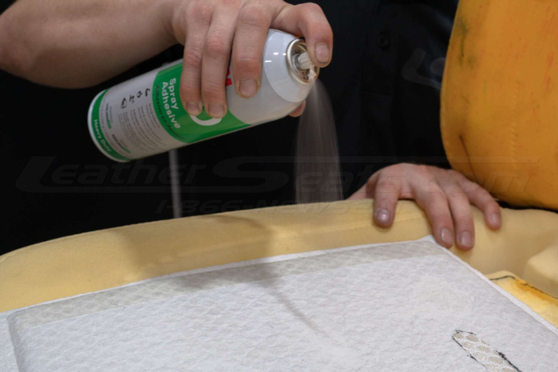
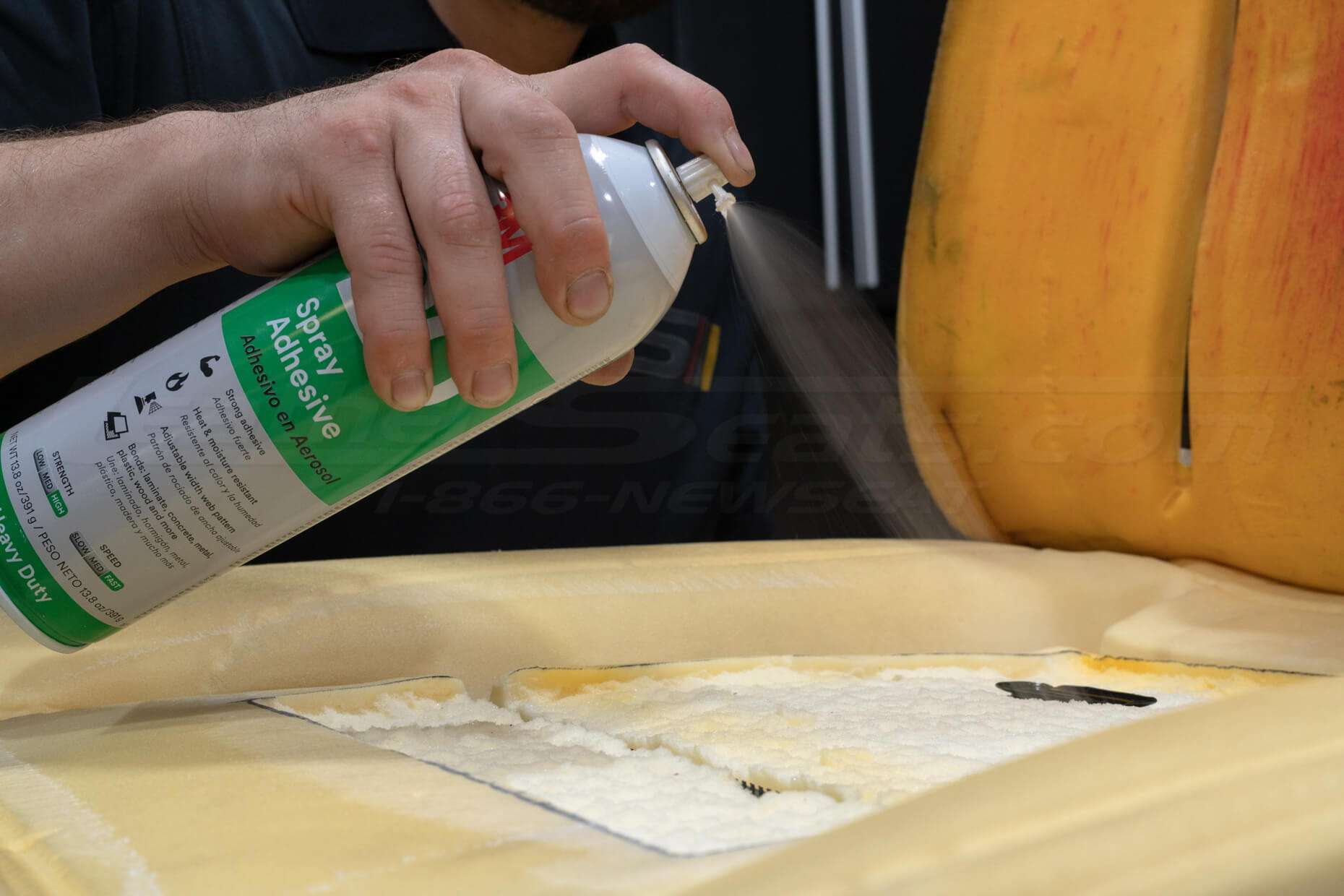
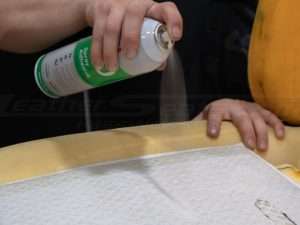
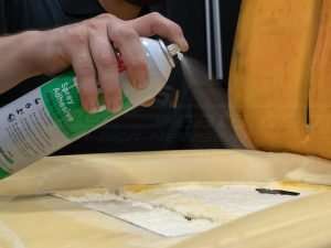
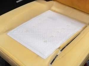
(Optional) Apply spray adhesive to seat foam and back of the distribution pad.
Remove the adhesive strip backing and mount the distribution pad to seat foam, making sure the TED output is aligned to the input of the distribution pad.

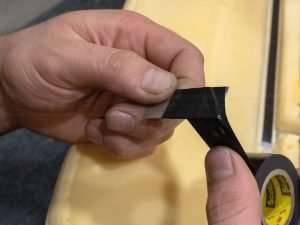
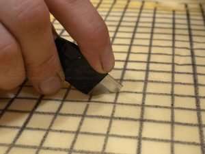
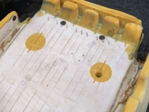
Modify Pad For Airflow (As Needed)
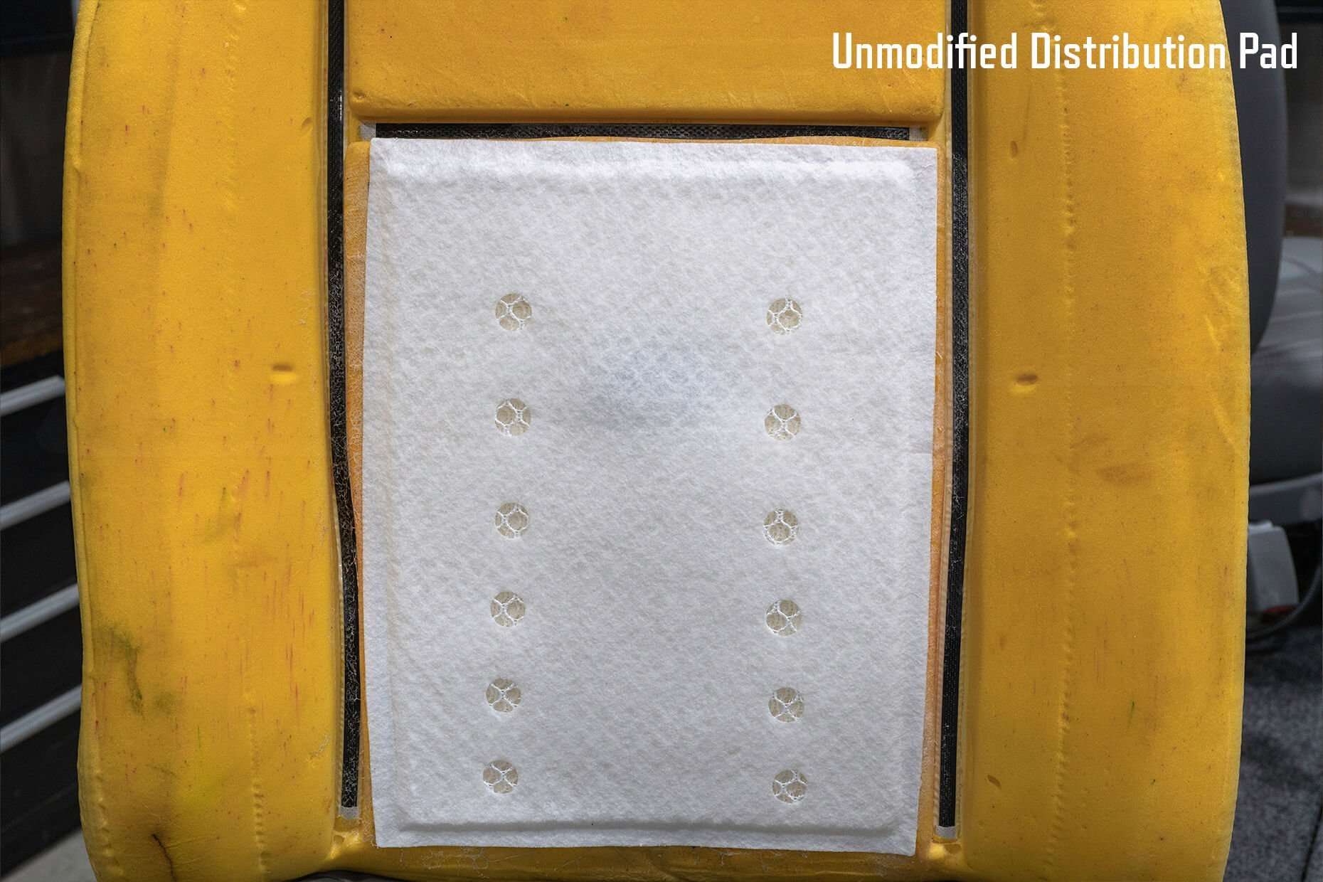
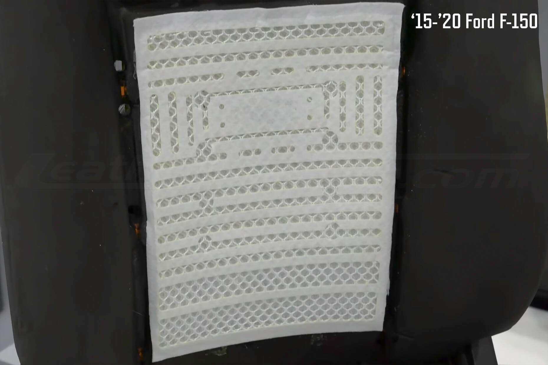
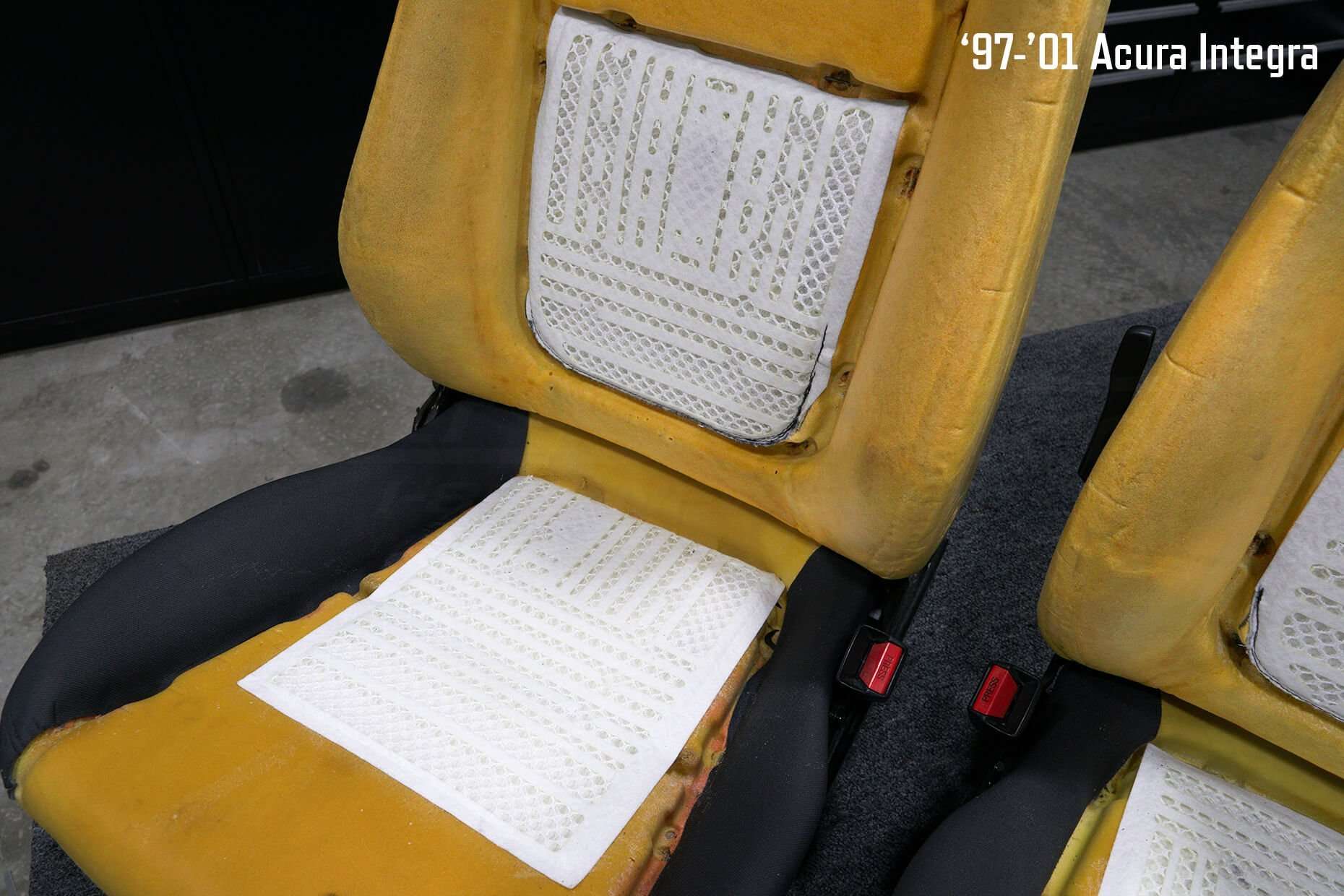
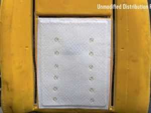
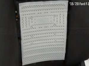
The outer layer of the distribution pad can be modified to optimize the airflow in specific areas of the seat.
Do not cut the outer layer of the distribution pad directly over the TED output. Ideally, you will want to create even air pressure throughout the distribution pad for proper airflow.
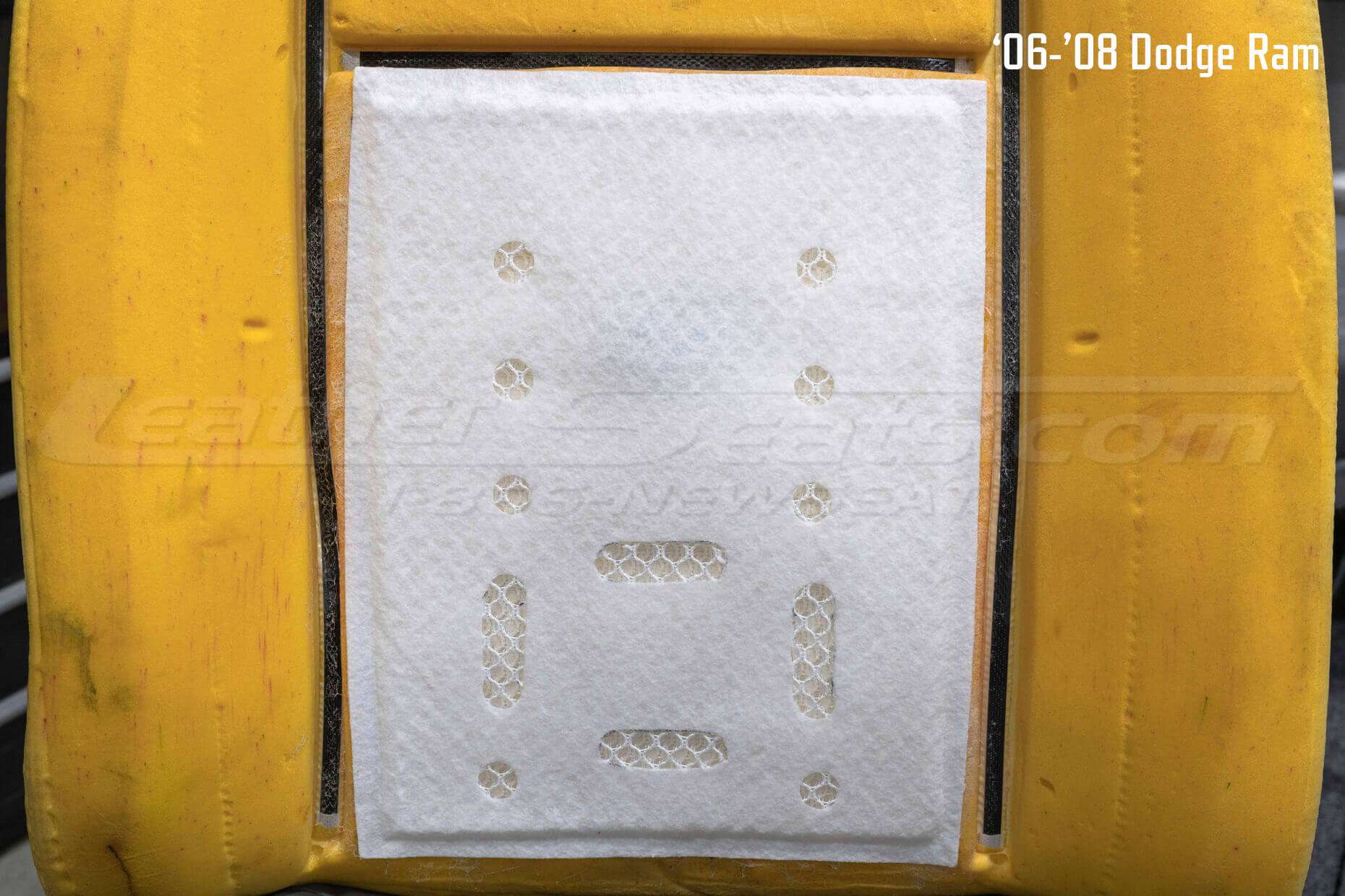
Modifications to the surface of the distribution pads are optional, however, we do recommend them. The logic to optimize airflow is to start from the TED output hole and work your way out. Keep the holes closest to the TED output smaller and make them larger as you move away. For later model F-150s, we have an example video that shows the modifications that we make to the distribution pads. This kind of modification does not require laser-cut precision like in the video, you can use a razor blade or sharp knife to cut the surface of the pad.
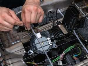
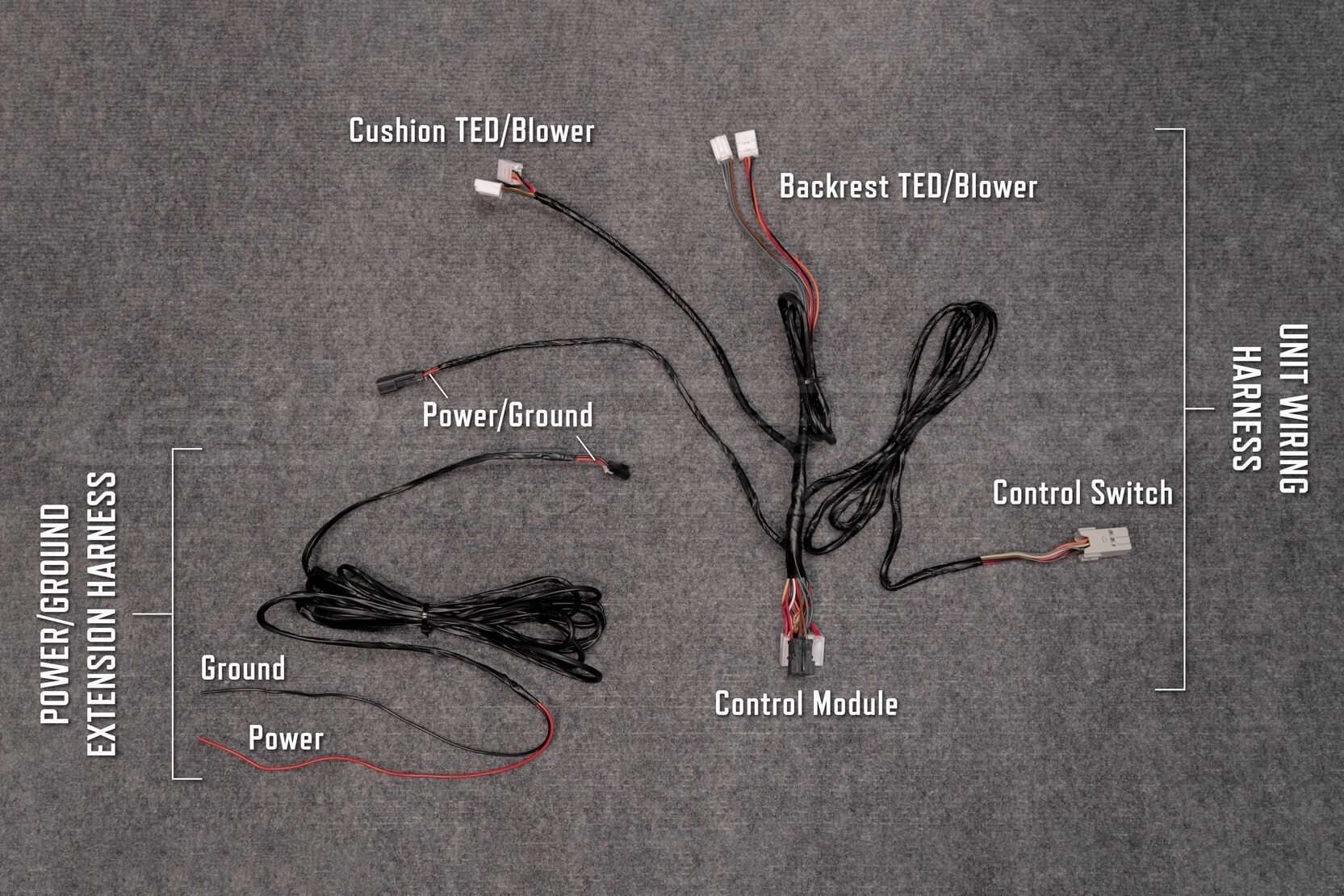
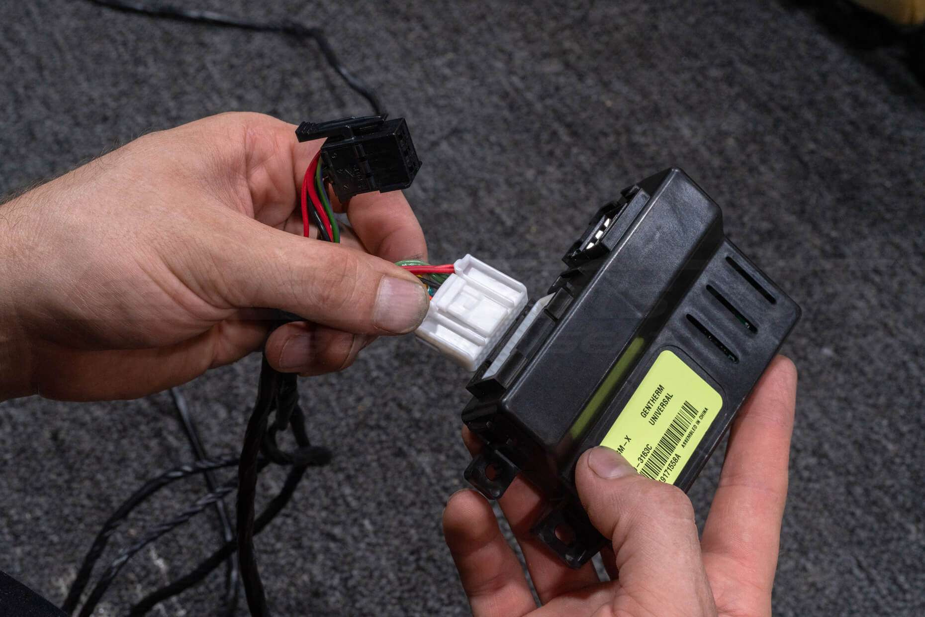
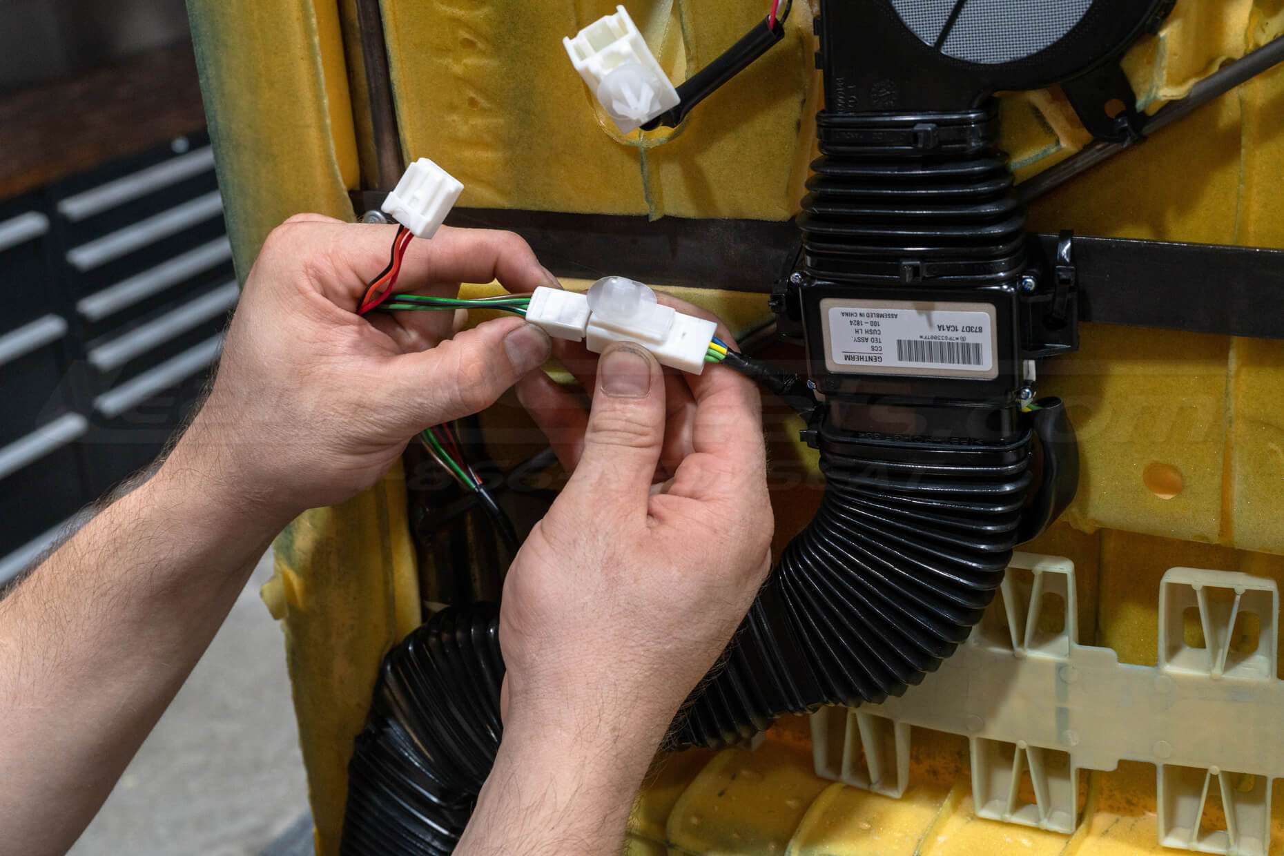
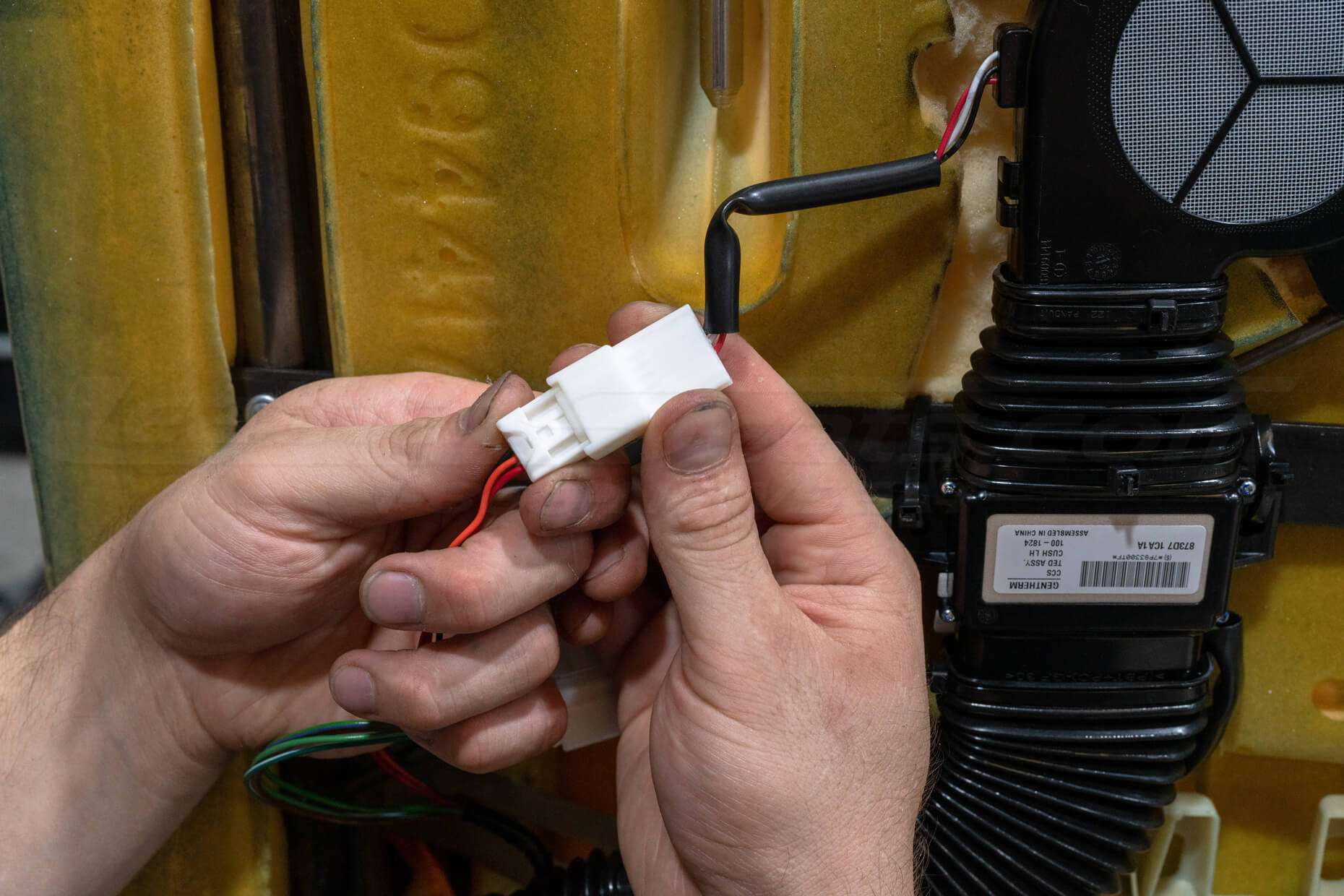
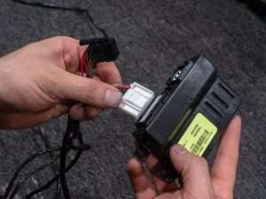
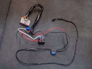
Connect Unit Wiring Harness and Control Module
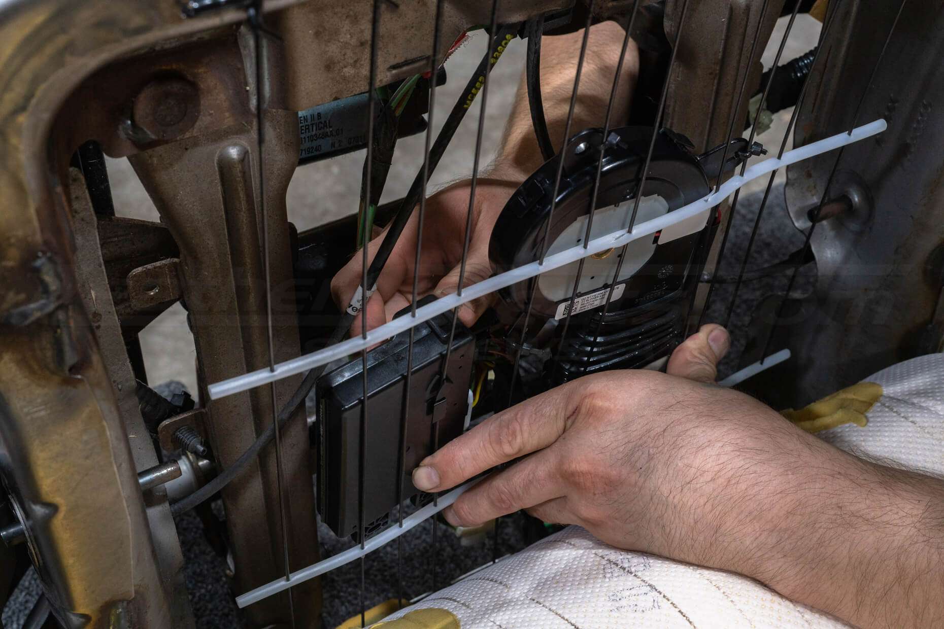
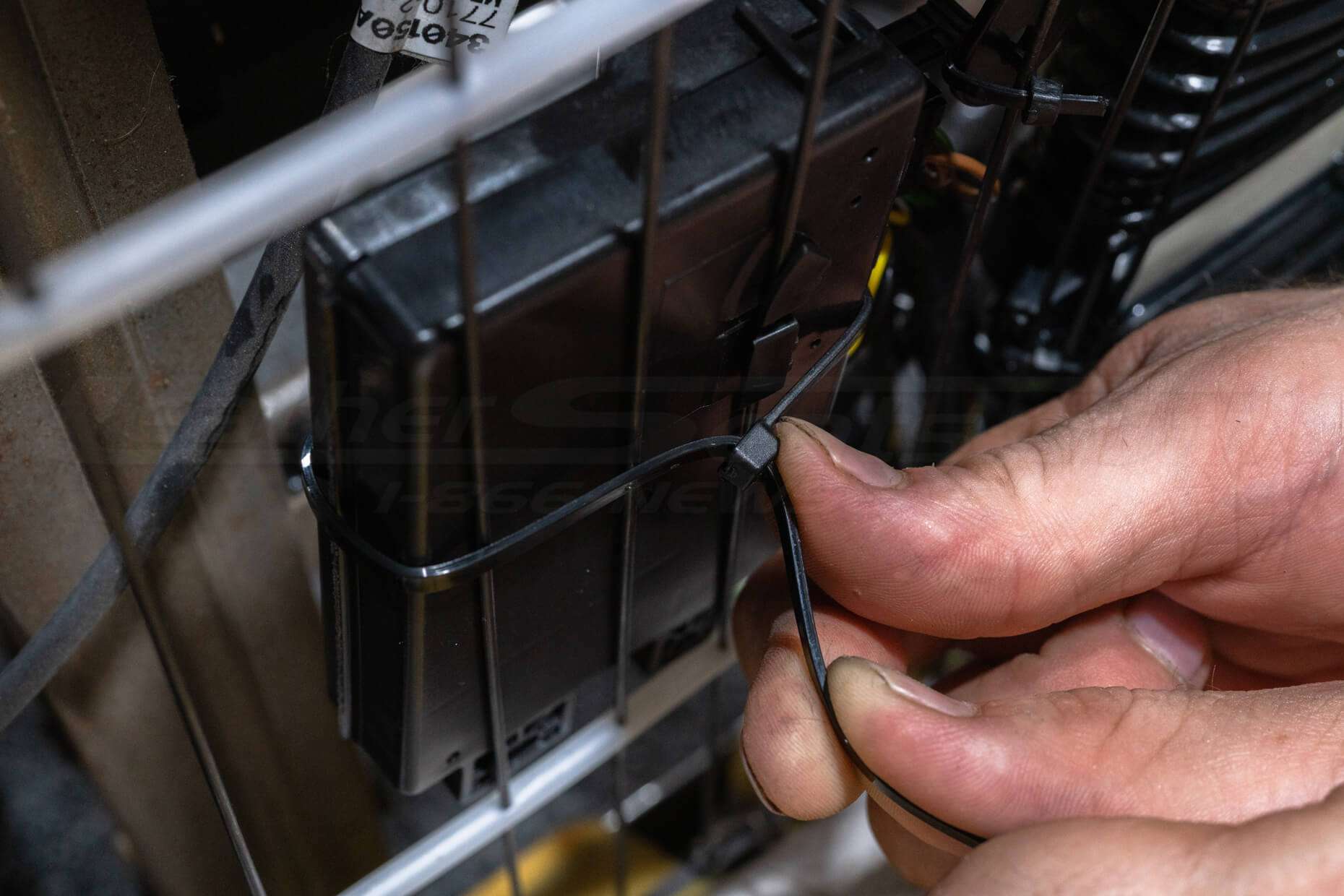
Typically under the seat will give you the most room to mount the control module, however, depending on your application, it can be mounted anywhere that the unit wiring harness can reach. You may want to plug the control module into the unit wiring harness before mounting for ease of access.
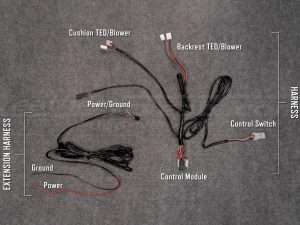
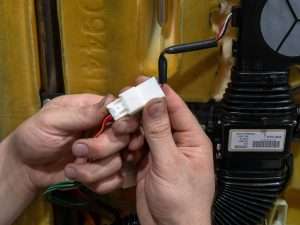
The unit wiring harness needs to be plugged into the TED units, blowers, control module, and control switch in order to power the entire system.
*Note, the backrest TED and blower wiring will be longer than the cushion TED and blower wiring.
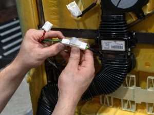
Bench Test System
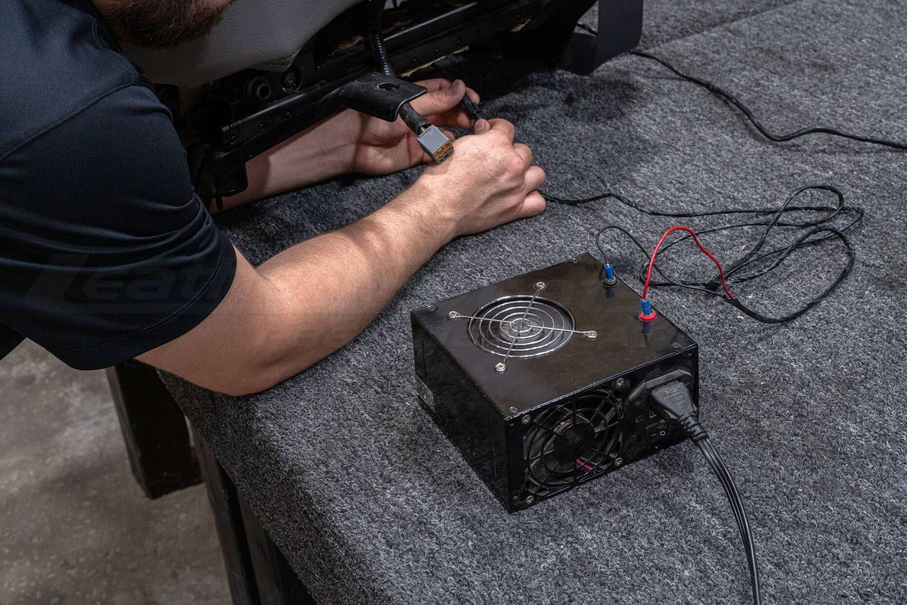
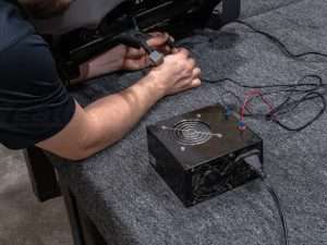
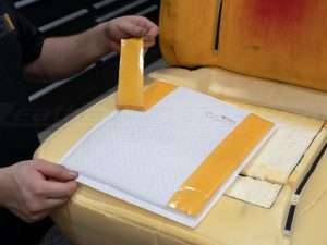
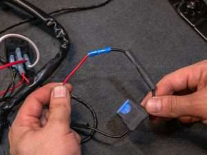
Before reinstalling the upholstery, bench test the system using an external 12V power source.
With all of the system components plugged in, connect the unit wiring harness to the power extension harness, and then connect the whole system to the 12V power source to bench test.
Cycle through all 6 settings of heating and cooling and make sure that you are getting sufficient airflow through the distribution pads. For the most accurate airflow testing, sit on the seats to check if any further modifications to the surface of the distribution pads are necessary.
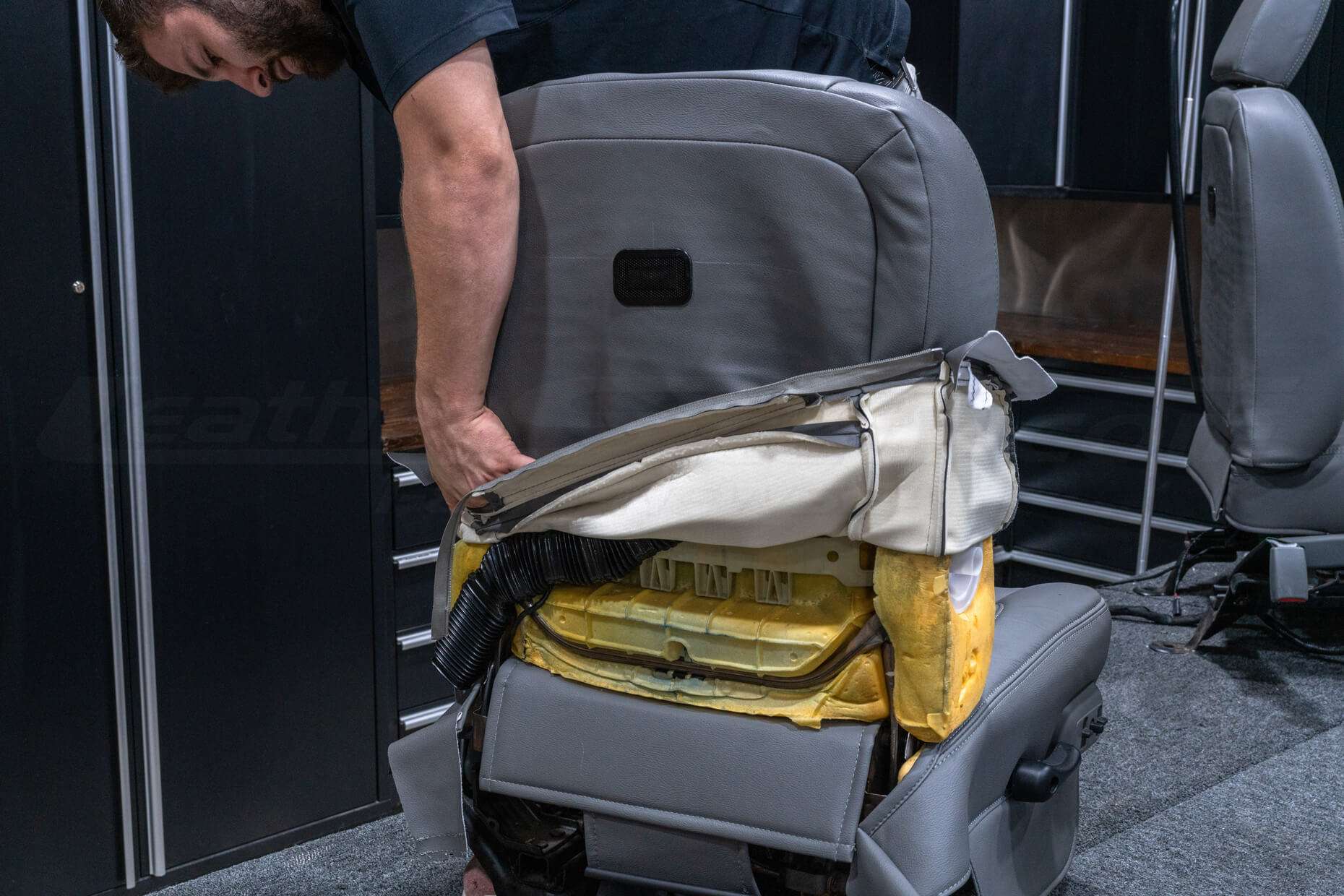
Install Upholstery
NOTE, before installing/re-installing the upholstery, make sure that it has perforation and a high-flow reticulated backing foam to ensure that the system has proper airflow.
If the seat upholstery is an open-back design with a hard shell, this will be the upholstery’s final placement. Be sure to double-check that there are no further adjustments needed to the Sanctum ventilation system and install the upholstery as you would normally.
If the seat upholstery is a closed-back design that limits the blower’s access to air, follow the next step to ensure proper function for the system.
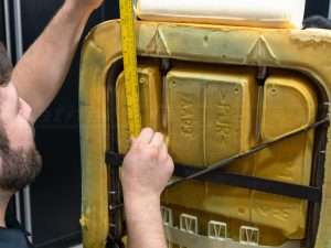
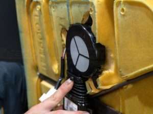
Install Intake Bezel (as needed)
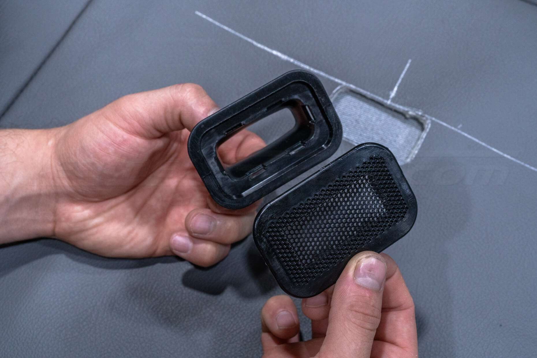
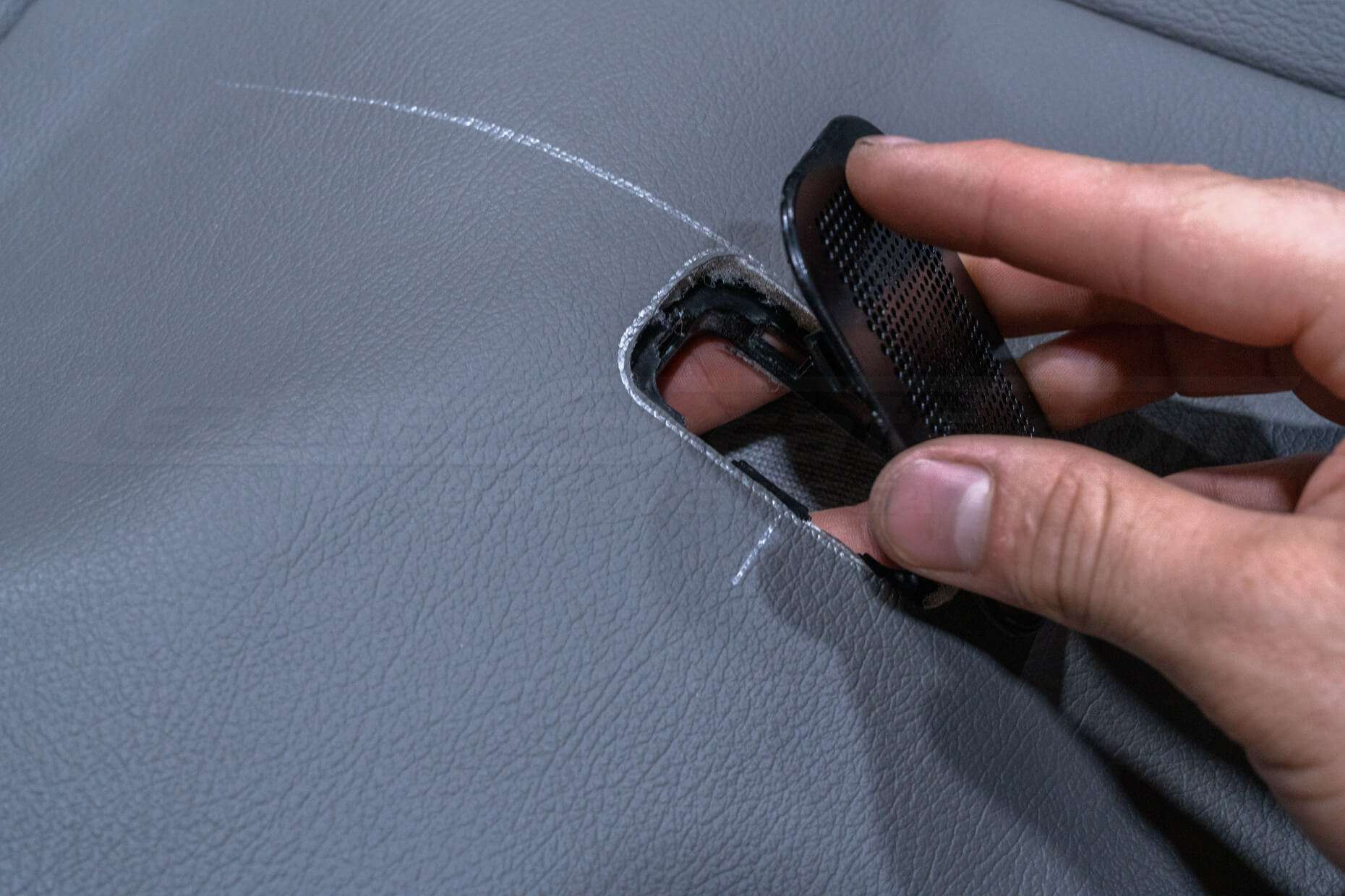
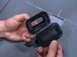
On seats with a fully enclosed backrest cover, the included exhaust bezel must be repurposed as an air-intake for the backrest blower.
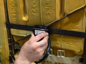
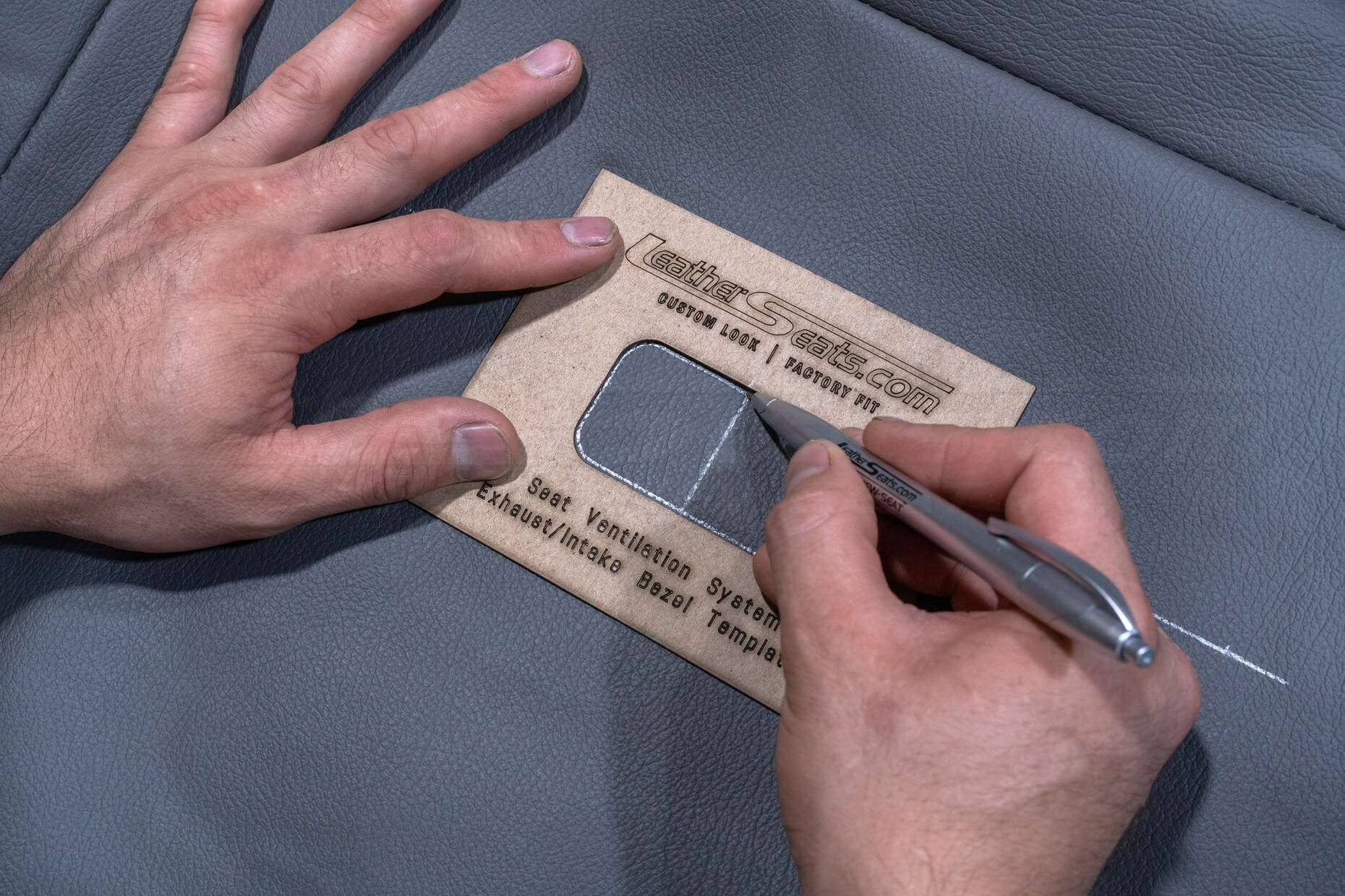
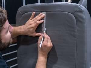
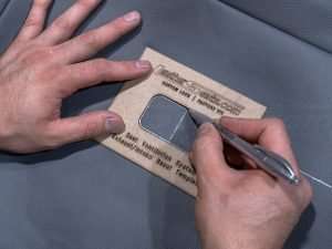
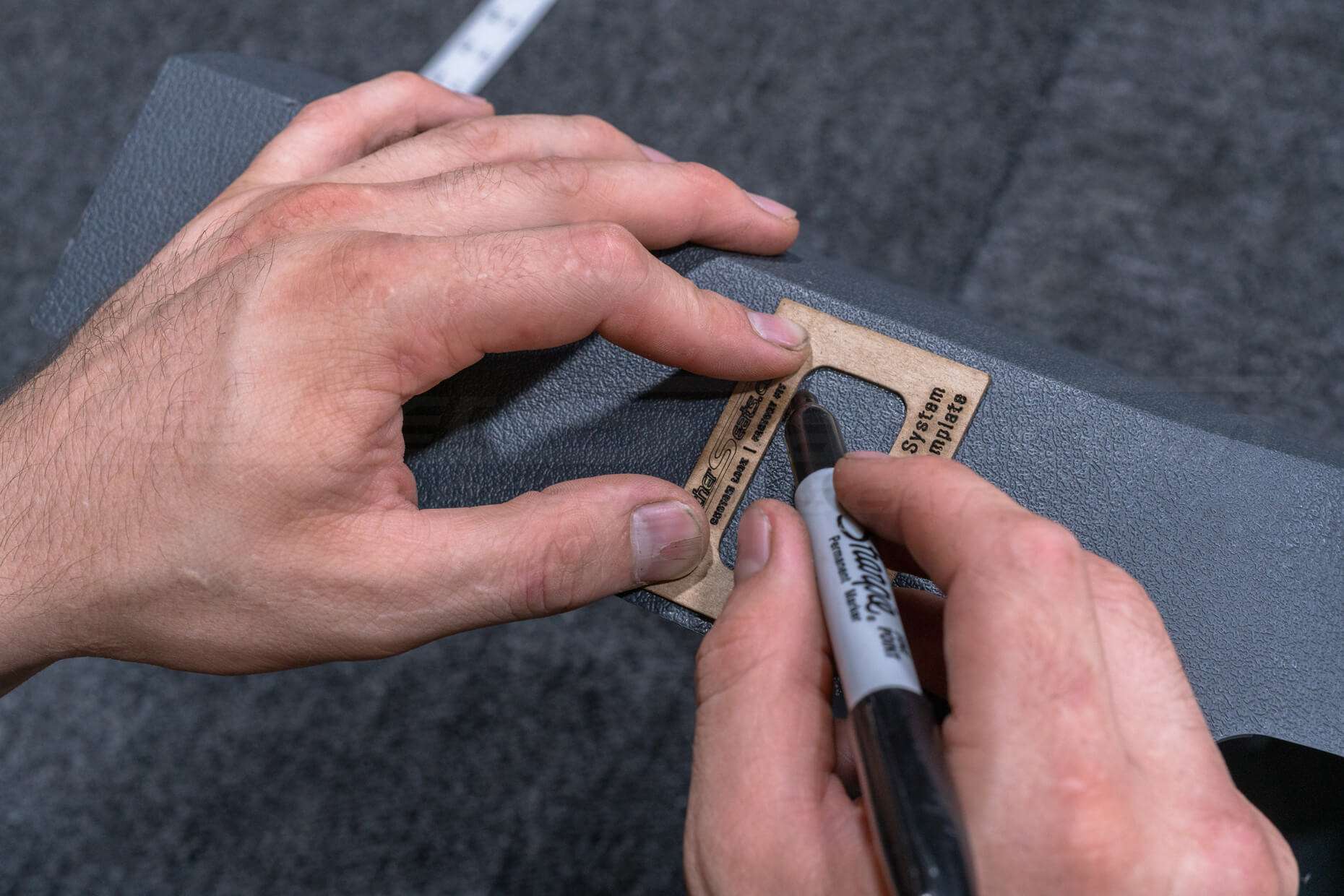
With the backrest cover installed, mark the placement of the bezel so that it sits directly in line with the blower. Use the included bezel template to trace the hole’s outline.
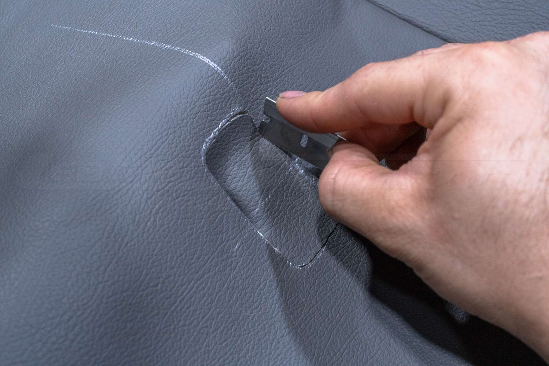
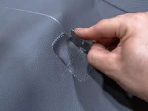
Remove the backrest cover, cut the hole, and install the intake bezel.
Reinstall backrest cover into its final position.
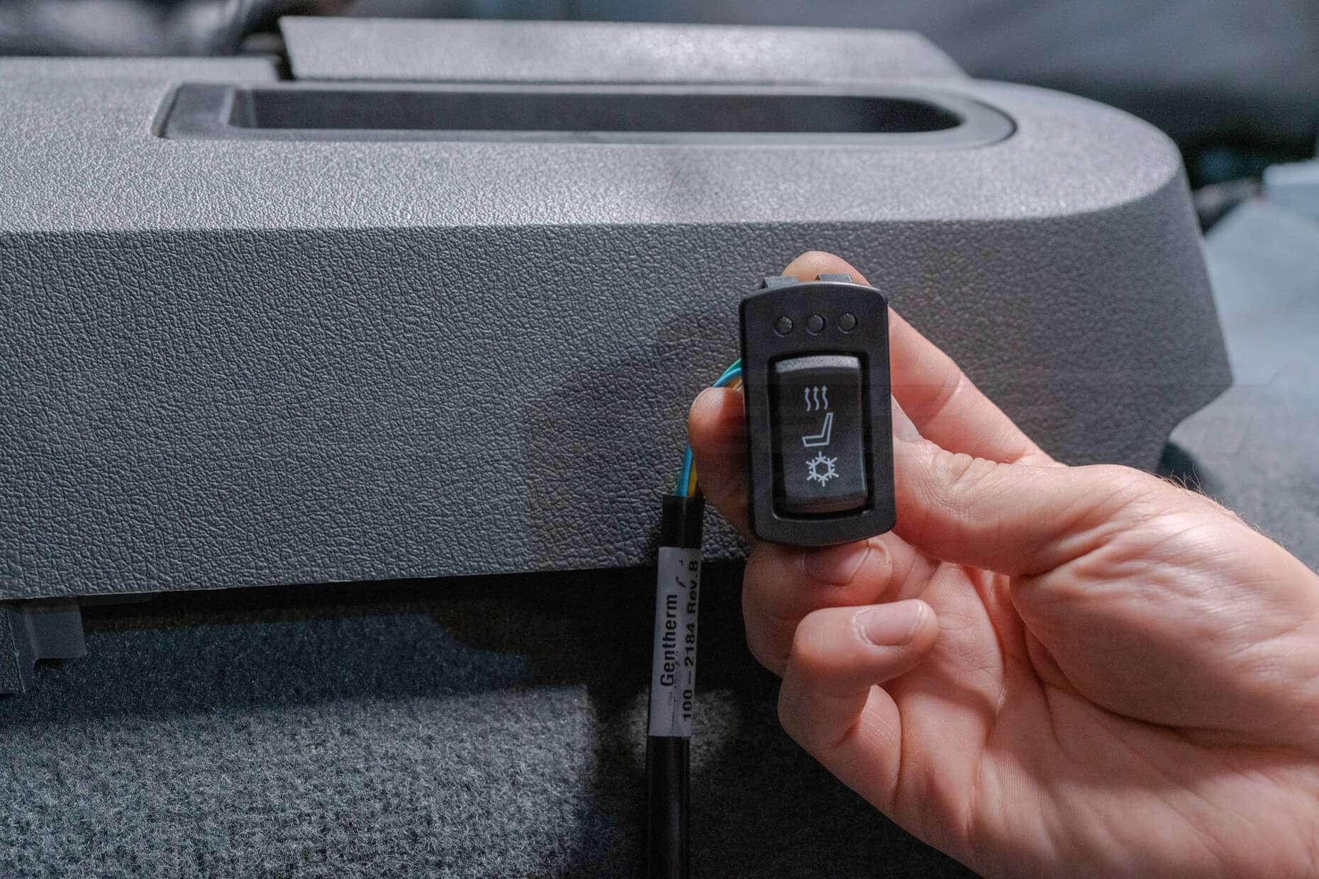
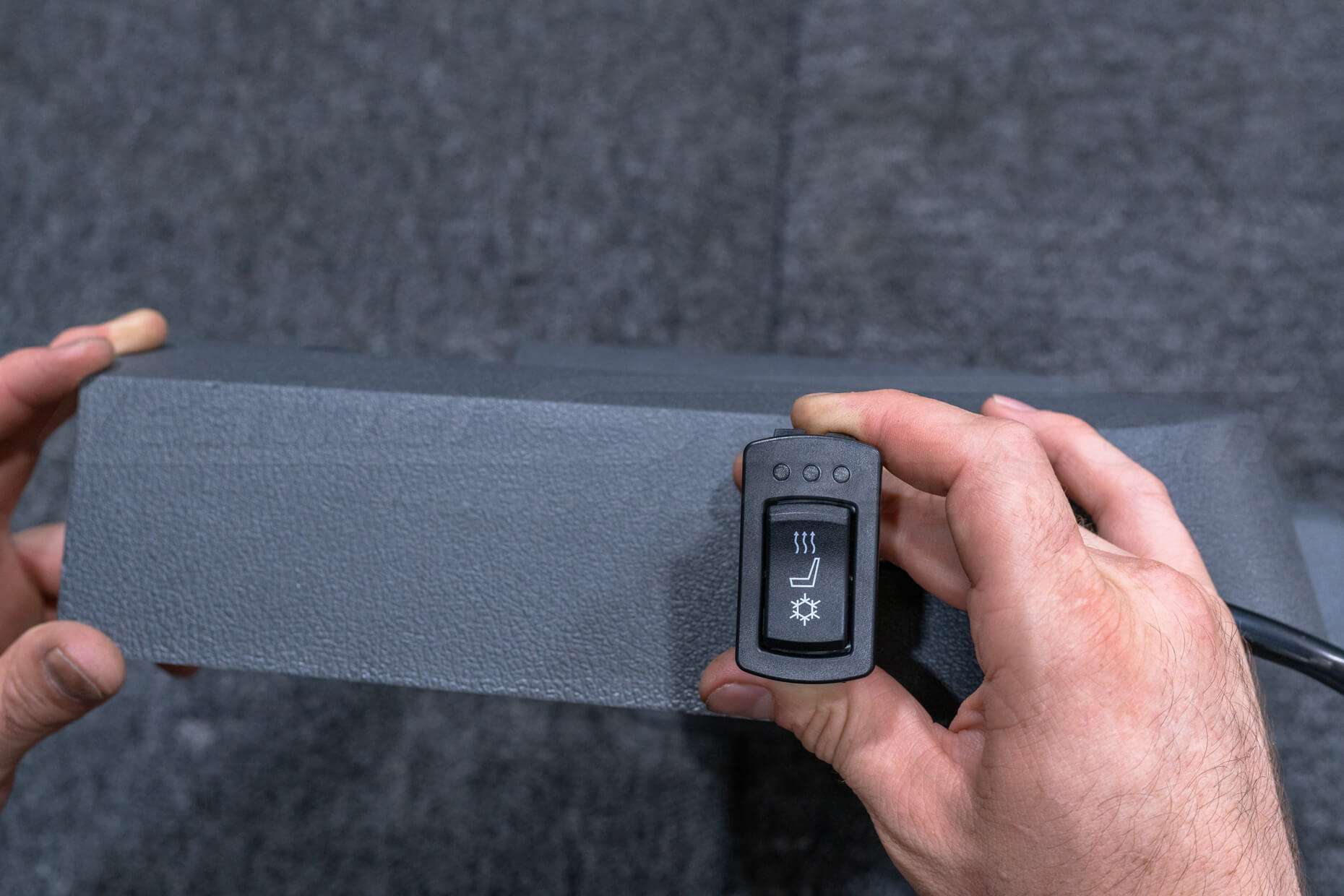
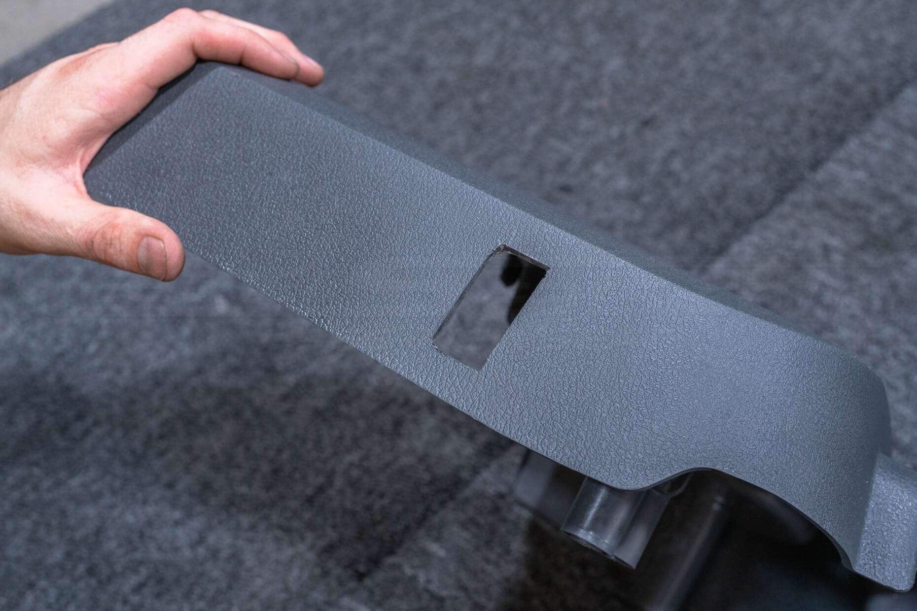
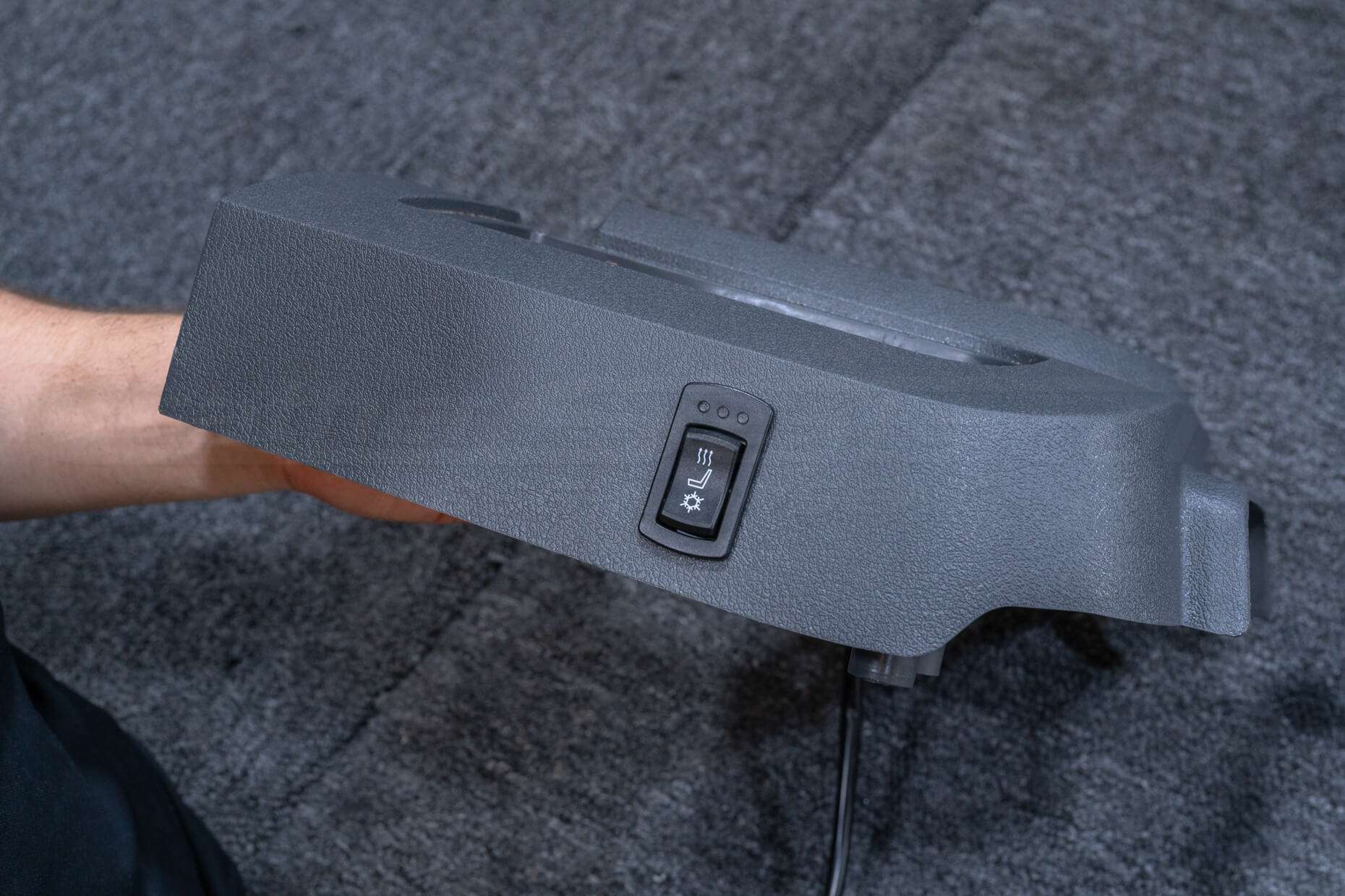
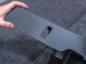
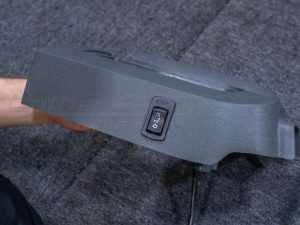
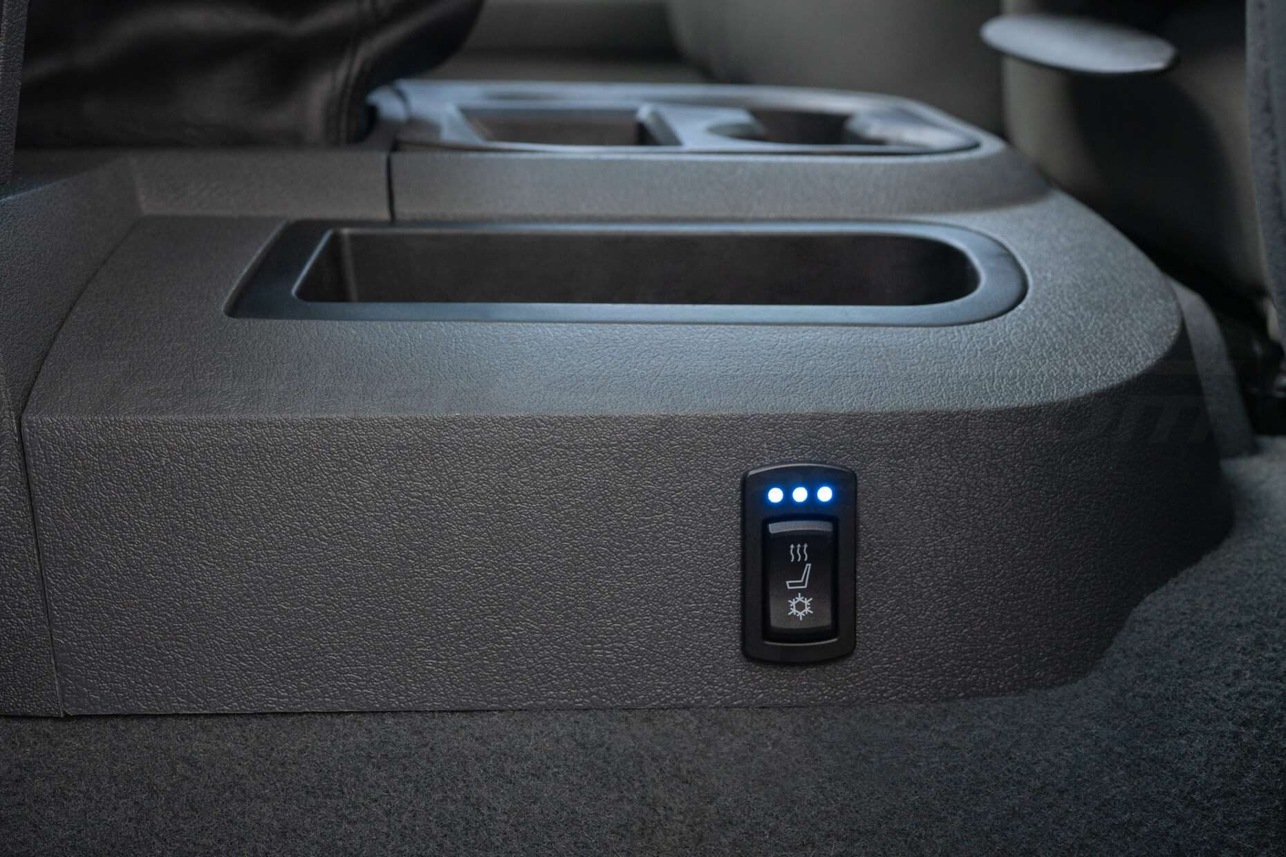
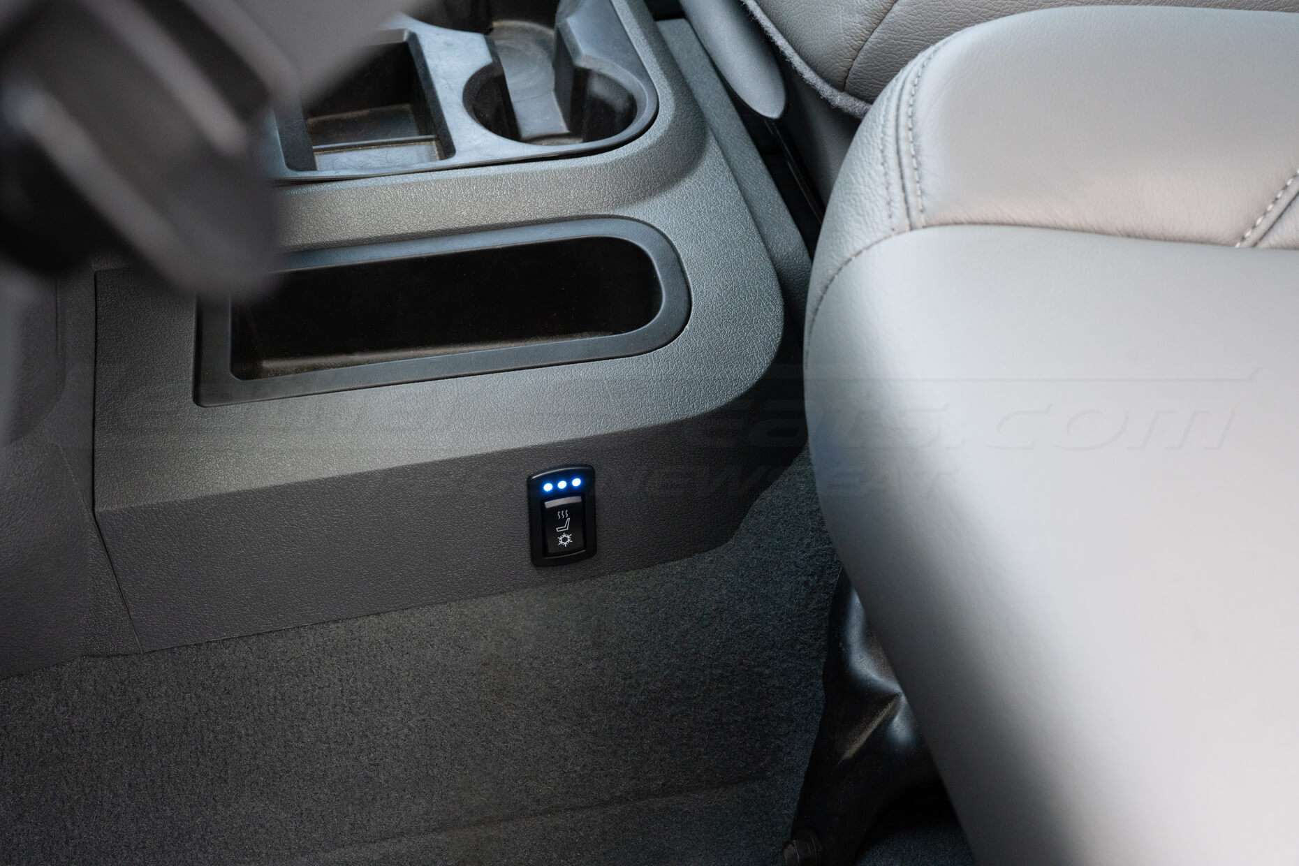
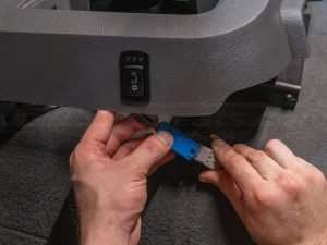
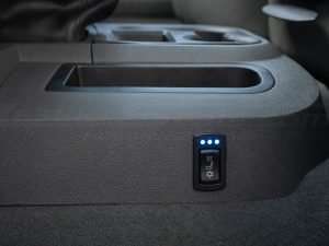
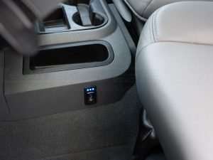
Switch Installation
Determine where you are going to mount the switch as switch placement will vary from interior to interior. Be sure there is enough room behind the mounting surface for the switch body and wiring harness.
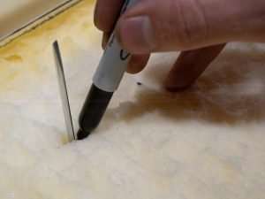
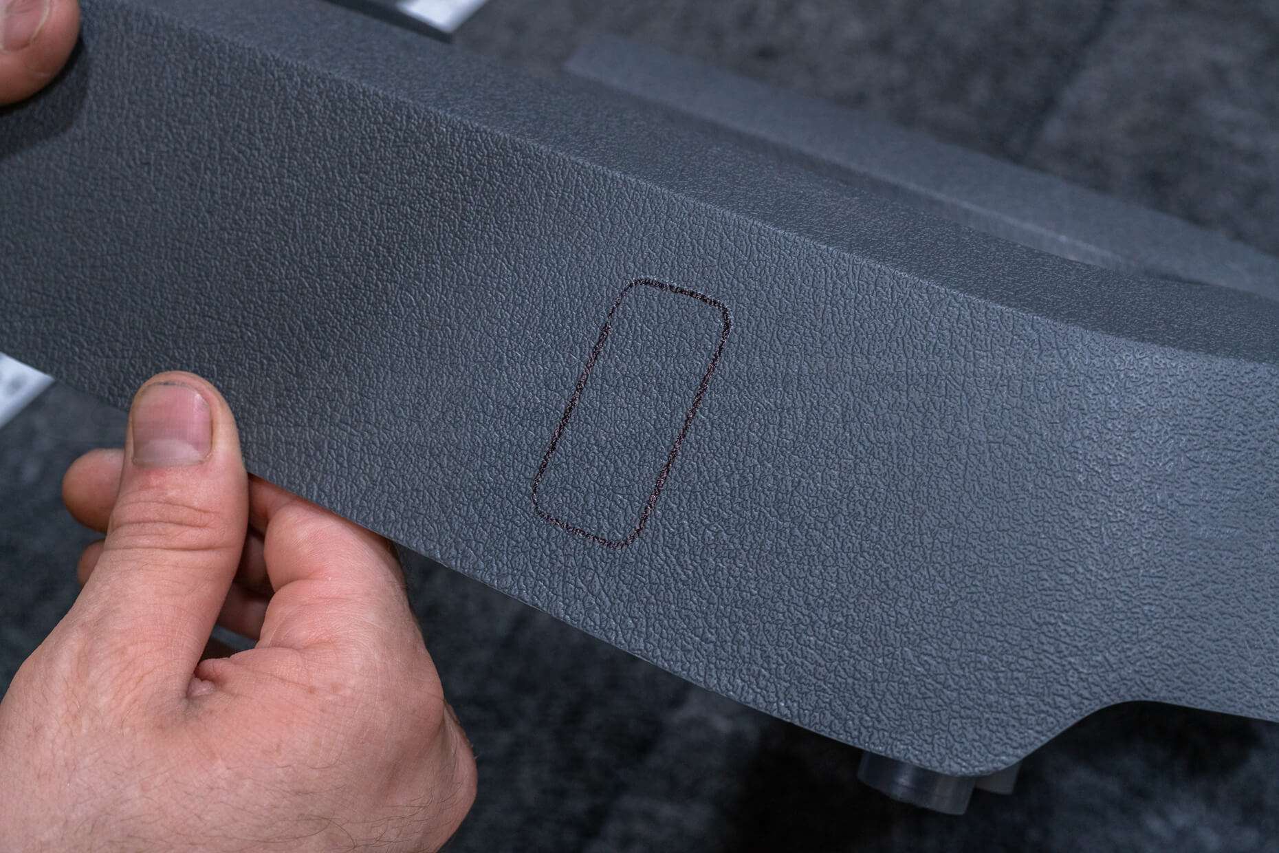
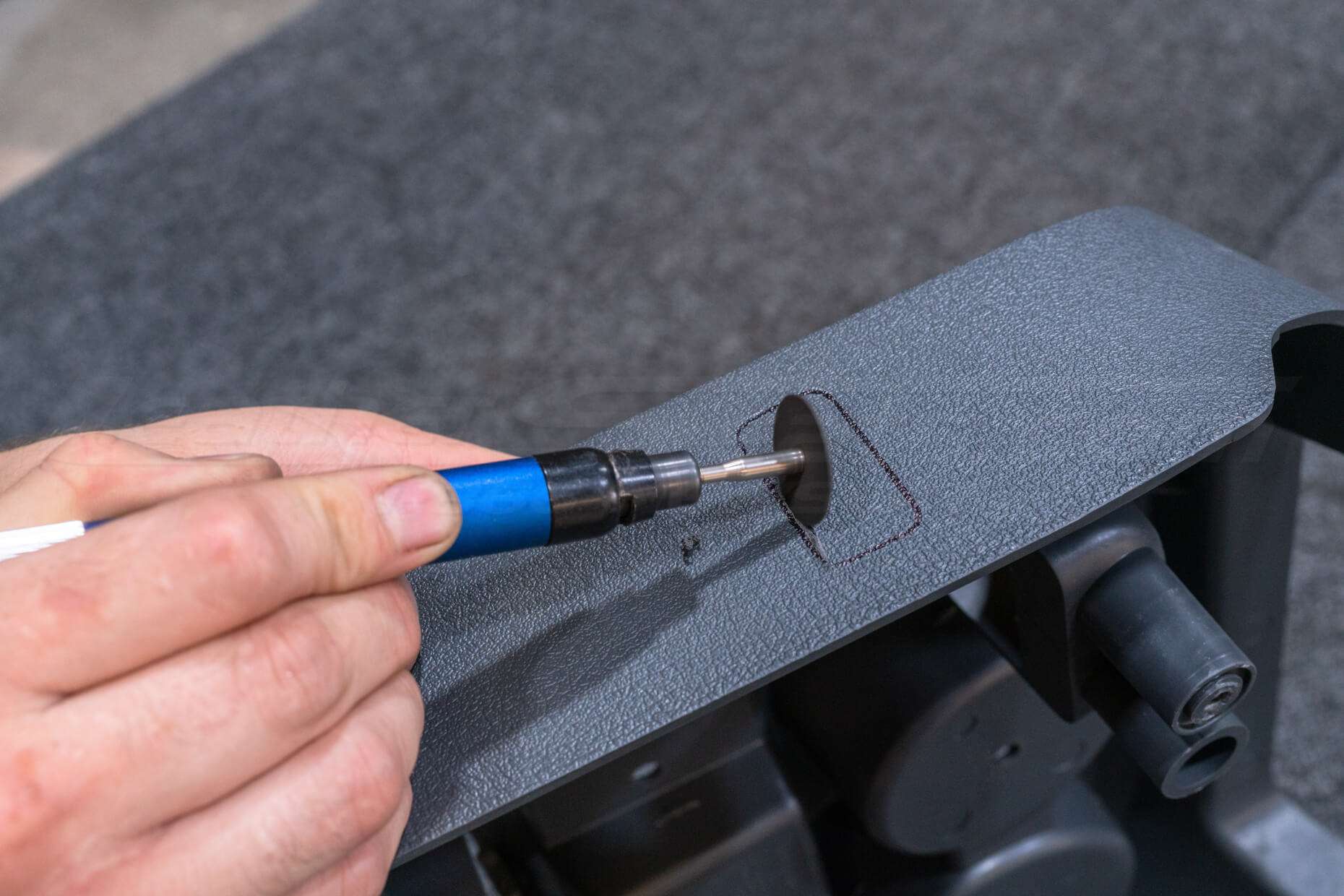
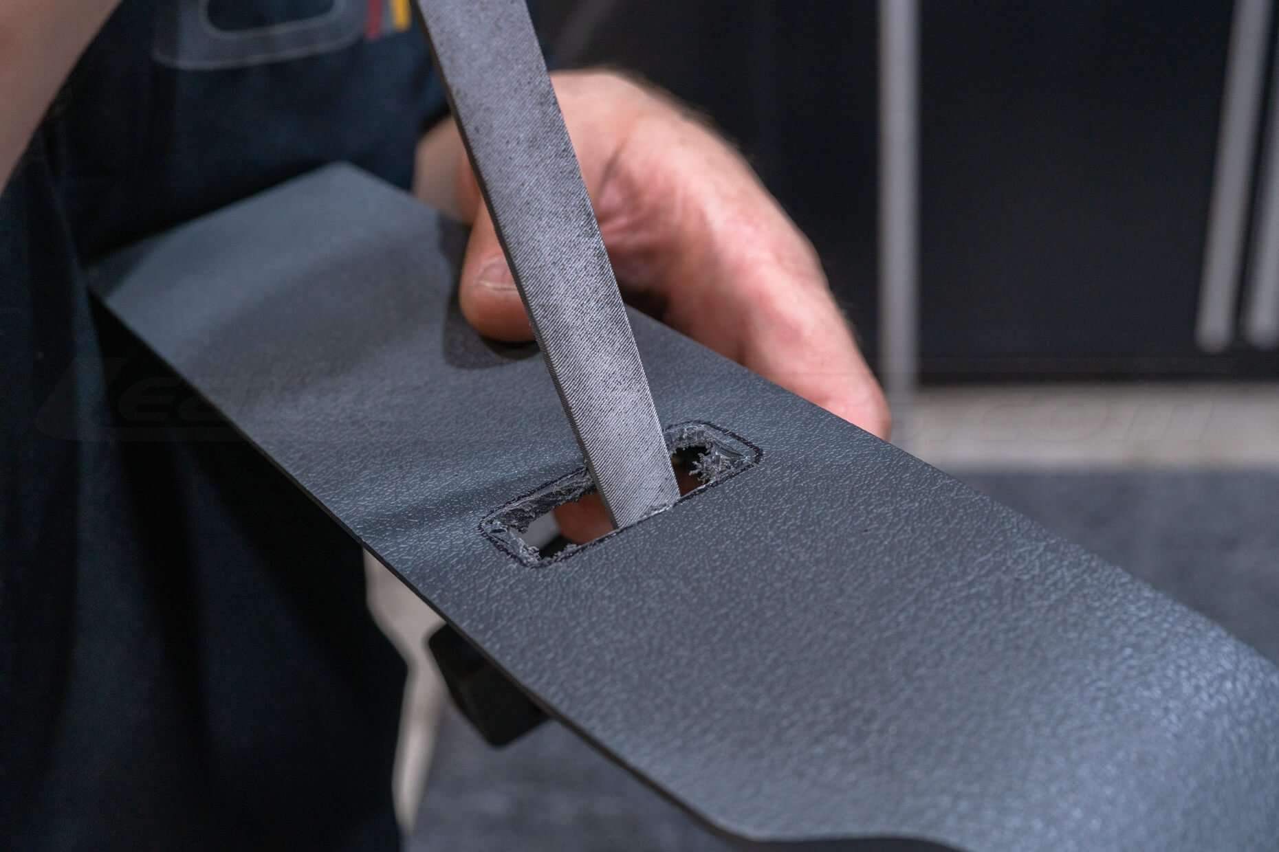
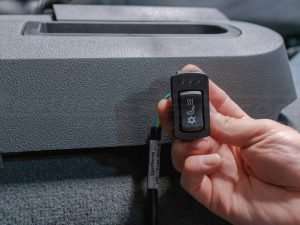
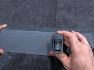
Use the provided switch template to trace and cut the hole for the control switch. There are a number of methods to cut out the holes and will be up to you to decide what is best for your situation.
Install switch and route the switch wiring back towards the main wiring harness.
Wiring
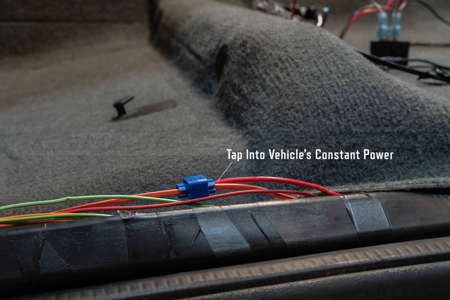
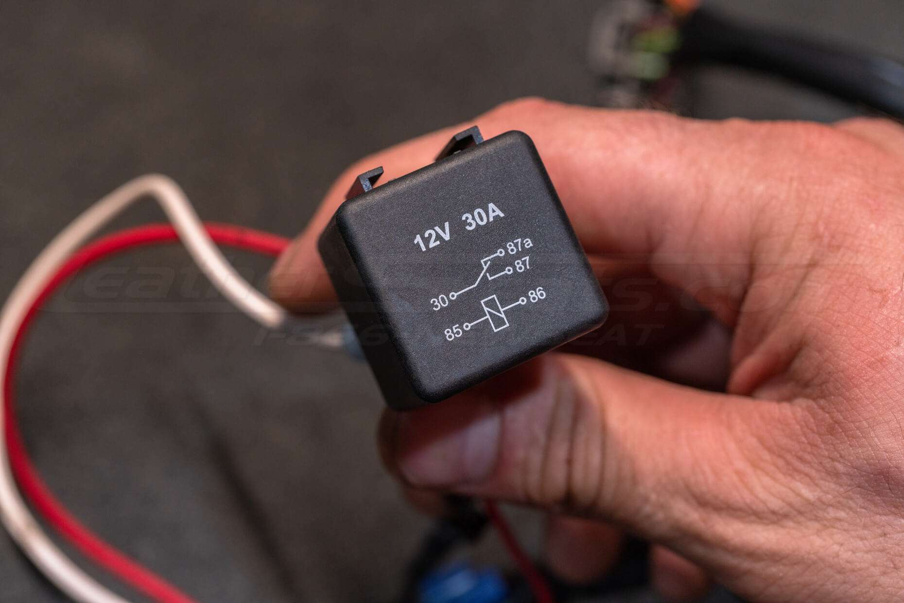
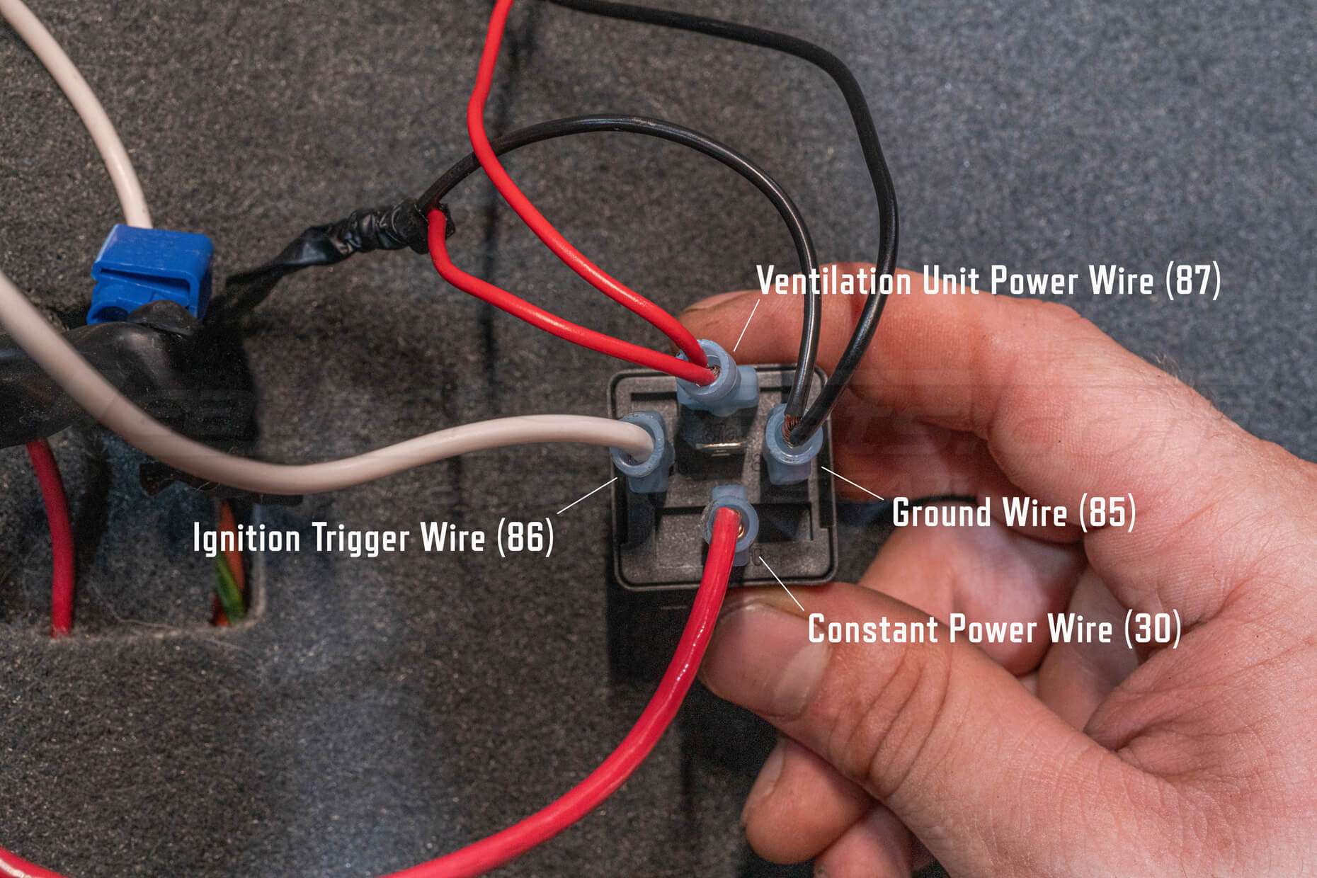
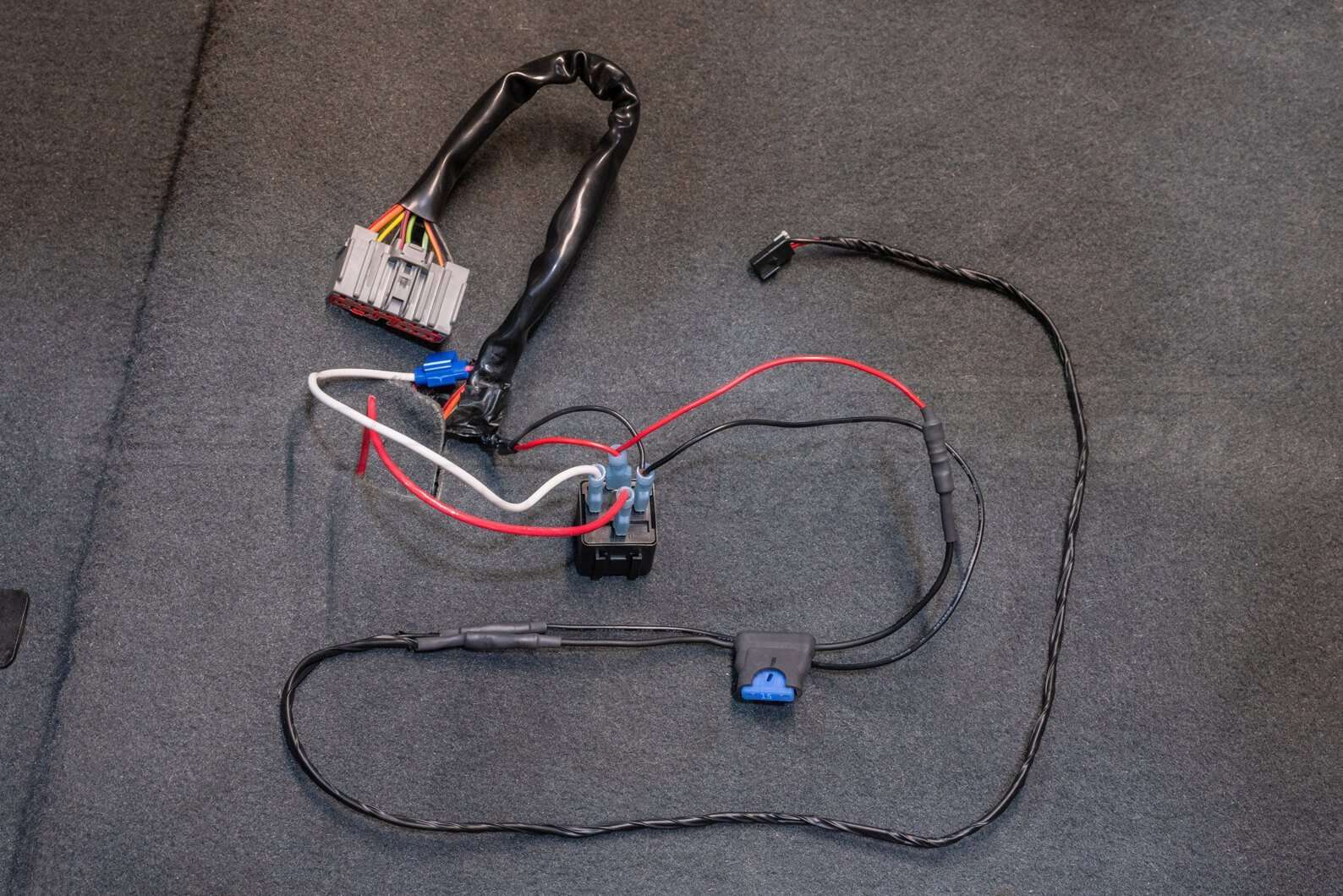
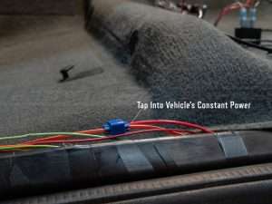
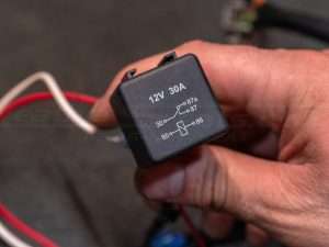
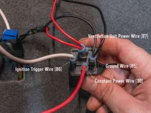

Tap a wire into a constant 12v power source rated for a minimum of 15 amps for one unit, or 30 amps for two units. Connect your 12v constant tap wire to pin 30 on the included relay.
Tap a wire into an ignition switched 12v source. Connect this tap wire to pin 86 on the relay.
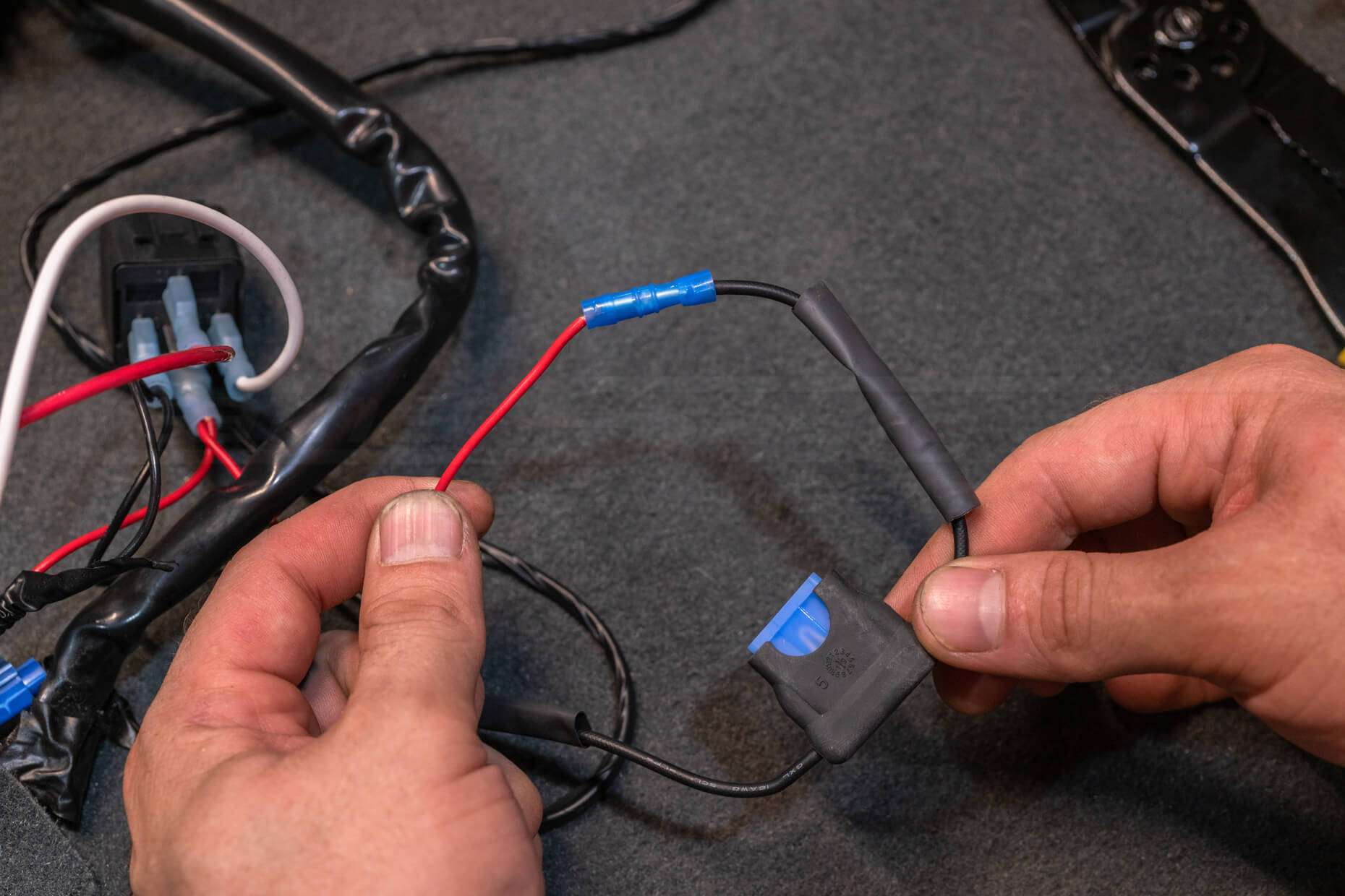
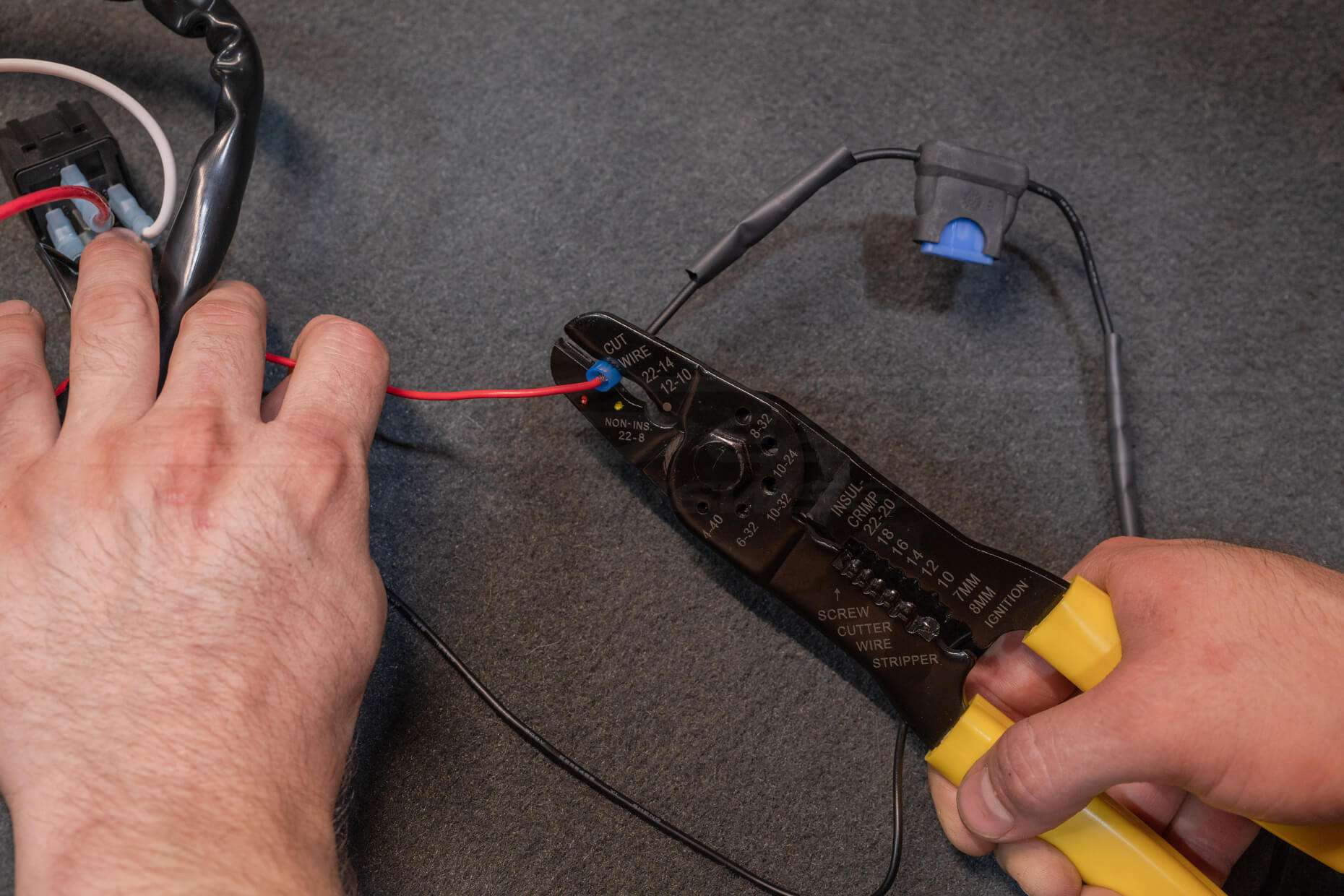
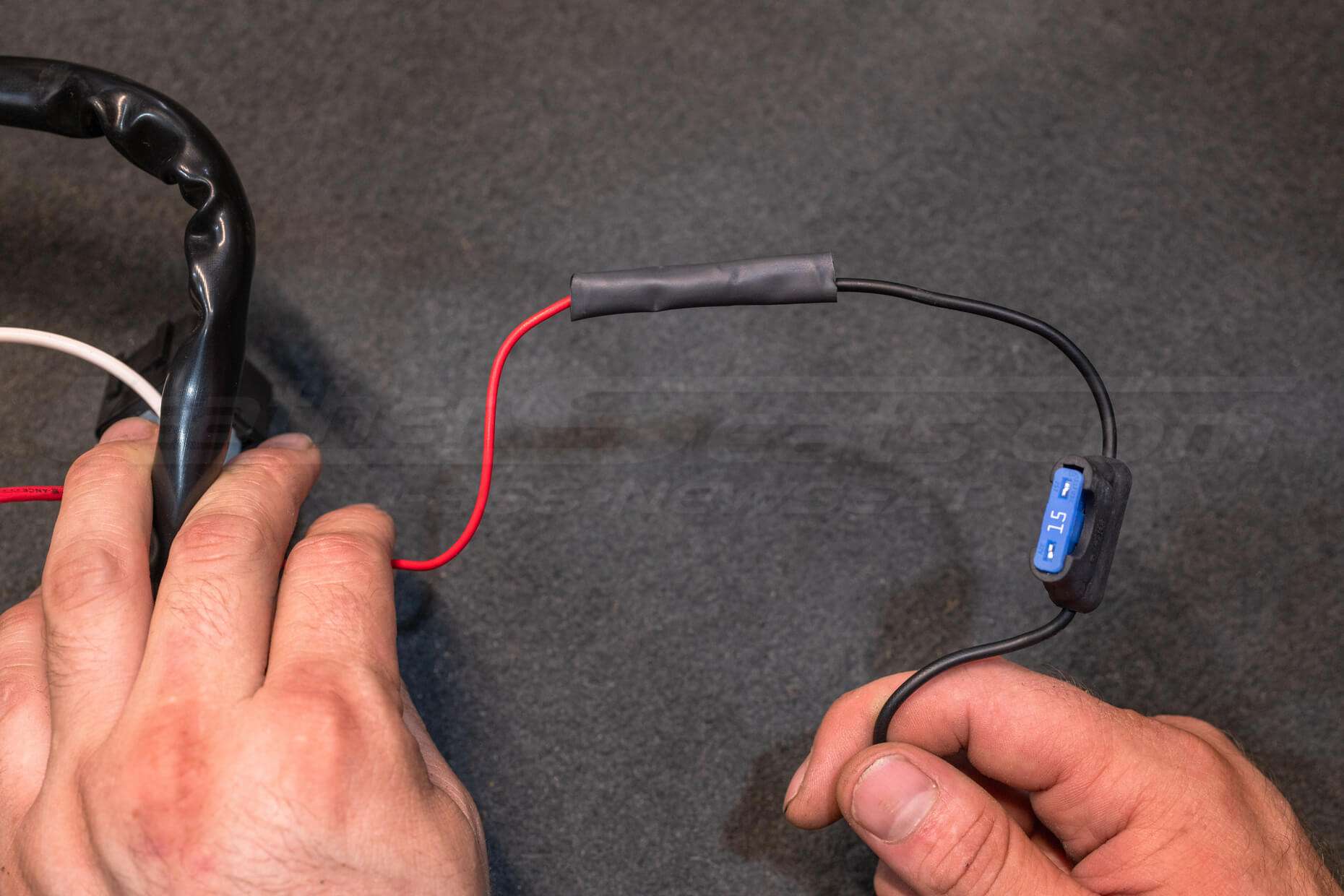
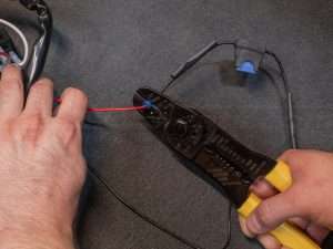
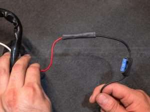
Connect the included 15A inline fuse to the positive wire on the power wiring harness.
Connect your fused power wire from the Sanctum system’s power harness to pin 87 on the relay.
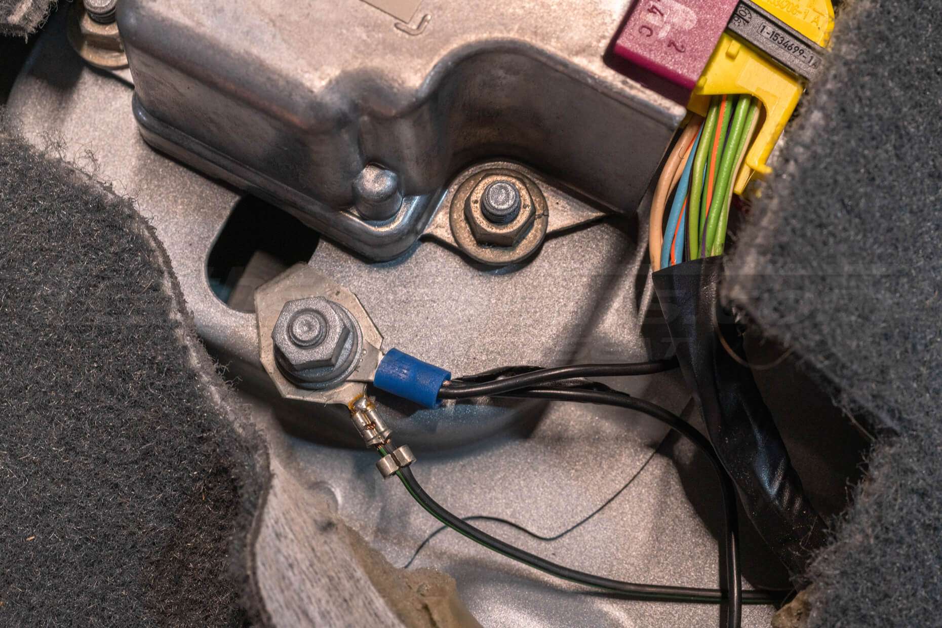
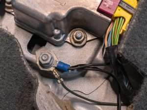
Connect pin 85 of the relay and the ground wire from the Sanctum system’s power harness to a suitable ground on the chassis or to an existing ground wire in the vehicle.
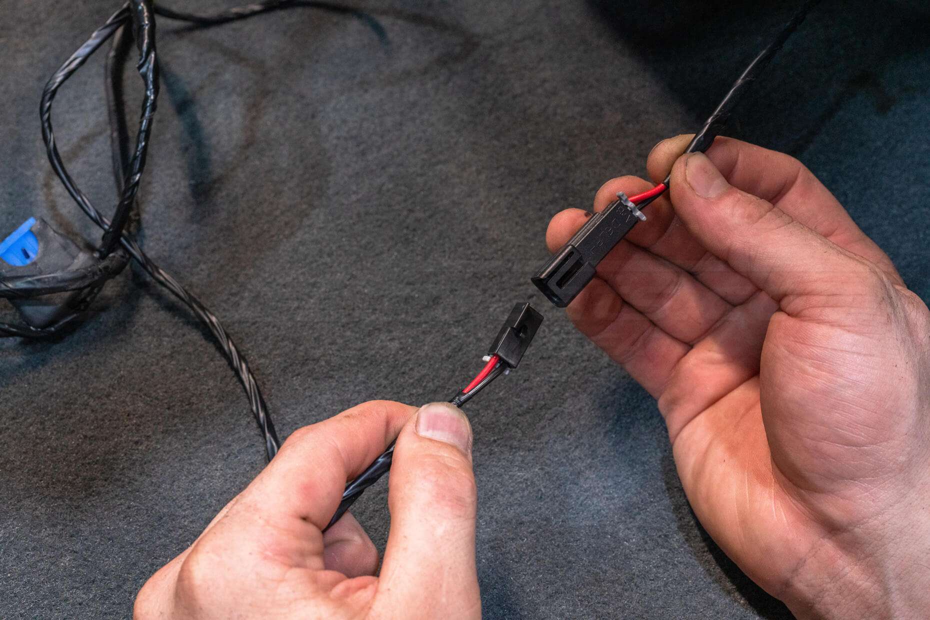
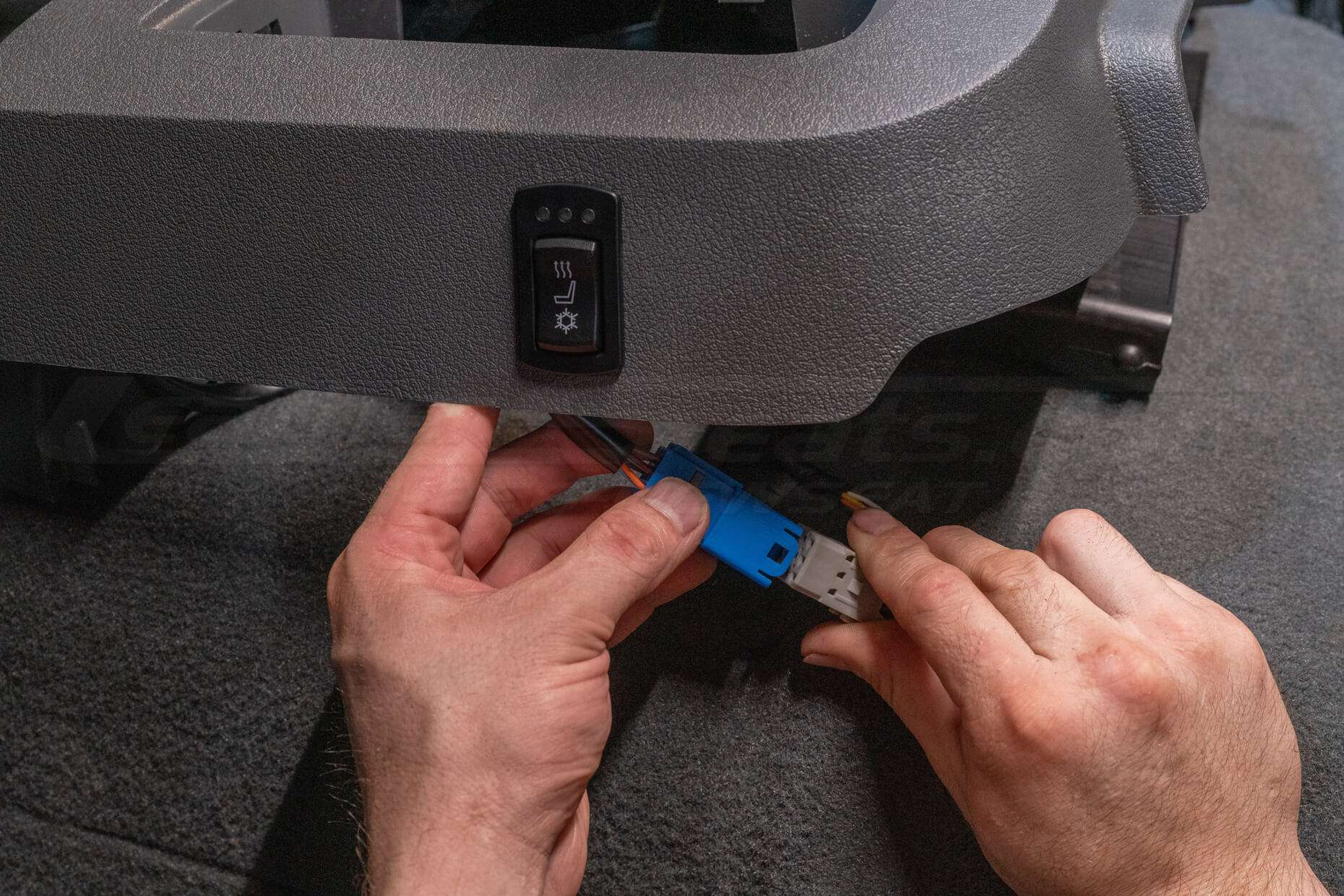
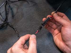
Reinstall seats into the vehicle, connect the switch to the seat’s wiring harness, and connect the power wiring harness to the seat’s wiring harness.
